
Advantages and Disadvantages of Surface Mount Technology (SMT)
To optimize your PCB design and assembly processes, it’s important to understand the pros and cons of surface mount technology. While SMT offers many advantages, it also has limitations that you need to be aware of. By following the guidelines in this article, you can take full advantage of SMT in your electronic designs.
The Evolution of Surface Mount Technology
SMT came about in the 1960s, and by the 1980s it was really starting to take off. By the 1990s, it had become the way to do PCB assembly, especially for high-end electronics. It replaced the traditional wire leads with metal tabs or end caps, so you could put the components right on the surface of the board. That let you use smaller components and do double-sided board assembly, which made it easier to automate and cut down on labor costs.
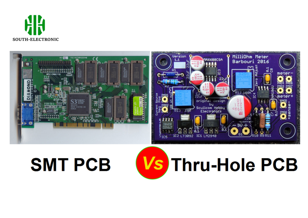
Key Features of SMT vs. Through-Hole Technology
SMT lets you mount components without drilling holes in the board. This is different from through-hole technology, where the leads on components go through holes. SMT components are usually smaller and can go on both sides of the board, which makes them good for high-density designs. On the other hand, through-hole components have stronger mechanical connections, but they cost more to make because you have to drill holes.
Comparison of SMT and Through-Hole Technology:
| Feature | SMT | Through-Hole |
|---|---|---|
| Component Size | Smaller | Larger |
| Assembly Complexity | Lower (automated) | Higher (manual/automated) |
| Manufacturing Cost | Lower (no drilling required) | Higher (requires drilling) |
| Mechanical Strength | Lower | Higher |
| Suitable for High-Density | Yes | No |
| Production Speed | Faster (automation friendly) | Slower |
| Rework and Repair | More Difficult | Easier |
Advantages of Surface Mount Technology
- Compact Design:SMT supports the miniaturization of electronic devices by allowing more components to be placed closer together. This results in lighter and more compact designs.
- Increased Component Density:Components can be mounted on both sides of the PCB, leading to higher component density and more connections per component.
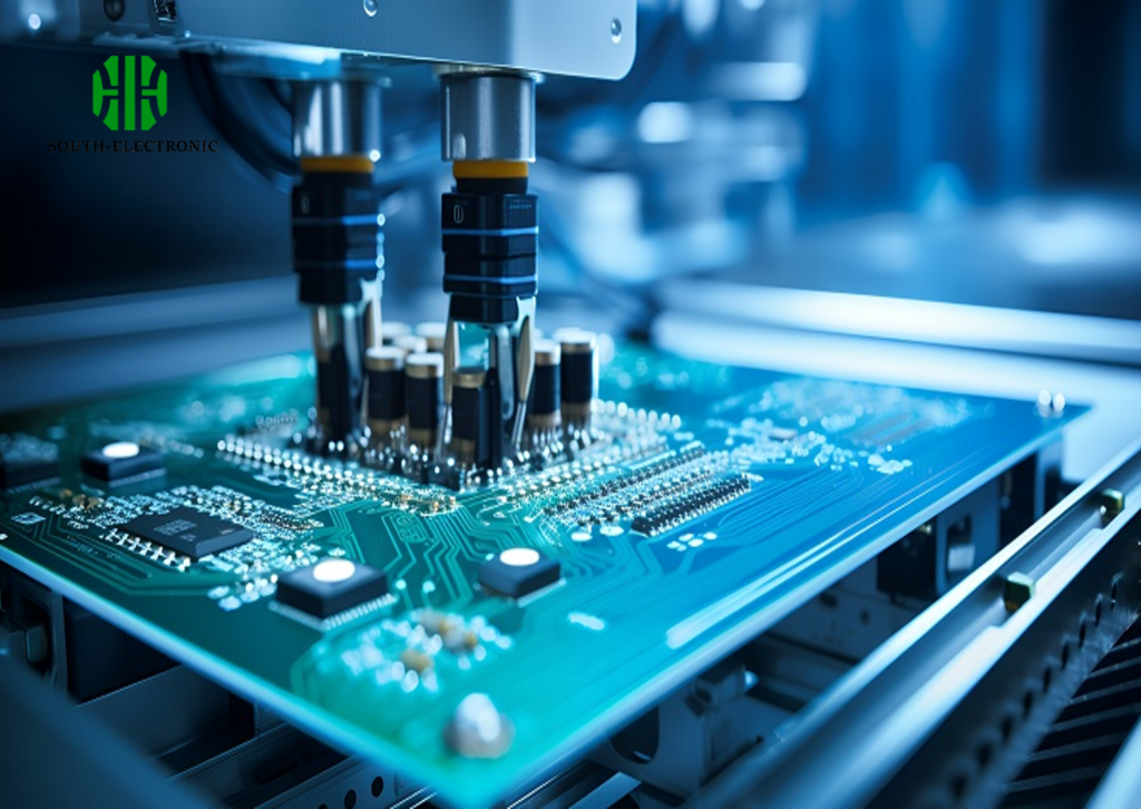
- Faster Production Setup:The use of solder paste for mounting components eliminates the need for drilled holes, speeding up the production process.
- Improved Signal Integrity:The shorter signal paths possible with SMT enhance signal integrity and reduce the potential for electromagnetic interference.
- Enhanced Automated Production: SMT facilitates higher levels of automation, making it suitable for large-scale production runs with lower labor costs.
- Better High-Frequency Performance:The reduced size and absence of leads in SMT components mitigate the effects of RF signals, improving high-frequency performance.
- Lower Resistance and Inductance: SMT connections have lower resistance and inductance, contributing to better overall circuit performance.
- Cost-Effective Material Handling:The compact nature of SMT components reduces board and material handling costs.
- Efficient Heat Dissipation: SMT designs dissipate heat more effectively, preventing overheating and ensuring stable performance.
Disadvantages of Surface Mount Technology
- Mechanical Stress:SMT components are less reliable under mechanical stress, as they lack the strong mechanical bonds provided by through-hole technology.
- Thermal Cycling Vulnerability:Solder connections in SMT can be damaged by thermal cycles, affecting the reliability of the components.
- Complex Repairs:Due to the small size of SMT components, repairs and manual assembly require highly skilled operators and specialized tools.
- Limited Marking Space:The smaller surface area of SMT components makes it difficult to mark part IDs and values, complicating prototyping and repairs.
- High Initial Investment:The equipment required for SMT, such as reflow ovens and pick-and-place machines, is expensive, increasing the initial setup cost.
- Solder Joint Reliability:The smaller solder joints in SMT can lead to concerns about joint reliability and potential void formation.
- Difficulty with High Heat Dissipation:SMT is not suitable for circuits with high heat dissipation, as the solder can melt under intense heat.
- Inspection Challenges:The compact size of SMT components makes the inspection process more difficult, increasing the chance of defects like solder overflow and short circuits.
SMT Advantages and Disadvantages
| Advantages | Disadvantages |
|---|---|
| Compact and lightweight designs | Less reliable under mechanical stress |
| Higher component density | Vulnerable to thermal cycling |
| Faster production setup | Complex and costly repairs |
| Improved signal integrity | Limited marking space |
| Enhanced automation | High initial investment |
| Better high-frequency performance | Reliability concerns with solder joints |
| Lower resistance and inductance | Unsuitable for high heat dissipation |
| Cost-effective material handling | Difficult inspection |
| Efficient heat dissipation | Higher risk of solder overflow and short circuits |
If you want your design to be really small and thin, use surface mount. Surface mount is great for high-speed and high-frequency stuff and for making lots and lots of something. It’s also good if you want your thing to be light and not make much noise.
Guidelines for SMT Component Placement
- Minimize Routing Distance: Place components as close as possible to reduce routing distance.
- Adhere to Signal Path: Follow the signal path as per the schematic during component placement.
- Avoid Sensitive Signal Paths: Do not place components in the return path of sensitive signals to maintain signal integrity.
- Position Bypass Capacitors Closely: For high-speed devices, place bypass capacitors near their power pins to reduce parasitic inductance.
- Group Power Supply Circuits: Arrange SMT components for power supply circuits together to facilitate shorter routing and lower inductance.
- Single-Sided Assembly: Try to keep SMT components on one side of the board to minimize costs associated with stencils and assembly.
- Proper Markings: Ensure all component names, polarities, orientations, and placements are clearly marked in the assembly drawing.
SMT is a game-changer in the electronic assembly biz. It’s totally changed how we mount electronic components on PCBs. Got questions about using SMT for your designs? Holler at us in the comments. We’re here to help!

