لوحات روجرز PCB
South-Electronic
توجه إلى South-Electronic للحصول على الجودة العالية، الموثوقية، والقيمة الممتازة التي تحتاجها في لوحات PCB الخاصة بك. استمتع بأفضل الحلول المتكاملة للوحات روجرز PCB لدينا – من التصميم إلى الإنتاج، نضمن لك الدقة، القوة، والالتزام بأعلى المعايير الصناعية.
لوحات روجرز PCB عالية الجودة بثقة
مرحبًا بكم في South-Electronic، وجهتكم الواحدة للحصول على لوحات روجرز PCB فائقة الجودة التي تتميز بخصائص عازلة ممتازة واستقرار حراري عالي. توفر لوحات روجرز PCB لدينا أداءً استثنائيًا، مما يجعلها مثالية للتطبيقات المتقدمة في الصناعات الحيوية. اختر من بين التكوينات أحادية الطبقة، ثنائية الطبقة، أو متعددة الطبقات المعقدة، المصممة لتلبية متطلباتك الإلكترونية الدقيقة. سواء كنت تعمل في مجال التكنولوجيا الفضائية أو تحتاج إلى لوحات PCB عالية الجودة للاتصالات، فإن لوحات روجرز PCB لدينا مصممة لتوفير الموثوقية والدقة. اعتمد على South-Electronic للحصول على الجودة الفريدة والاتساق في مشاريعك التقنية المتقدمة. تعزز لوحات روجرز PCB لدينا وظائف أجهزتك بسلامة إشارة ممتازة وتقليل المخاوف الحرارية. تعاون معنا لدفع الابتكار والنجاح في مجالك.

لوحات روجرز RO4350B™ PCB
تُعرف لوحات RO4350B™ PCB بمادة العازل ذات الخسارة المنخفضة، مما يجعلها مثالية للتطبيقات ذات التردد العالي. تُستخدم على نطاق واسع في هوائيات محطات القاعدة الخلوية ومضخمات الطاقة بفضل استقرارها الحراري الممتاز وتكلفتها الاقتصادية.
لوحات روجرز RO4003C™ PCB
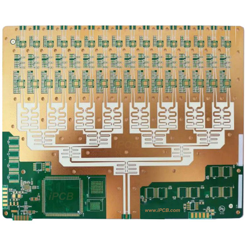
تتميز لوحات RO4003C™ PCB بثابت عازل منخفض وخسارة منخفضة، مما يجعلها مناسبة للتطبيقات الرقمية عالية السرعة وRF/الميكروويف. تُستخدم بشكل شائع في صناعات الطيران والدفاع، وخاصةً في تطبيقات الرادار والمستشعرات، بفضل أدائها الموثوق.

لوحات روجرز RT/duroid® 5880 PCB
تشتهر لوحات RT/duroid® 5880 PCB بثابت العازل والخسارة المنخفضين للغاية، مما يجعلها مثالية لتطبيقات الميكروويف والموجات المليمترية الحيوية. تُستخدم في أنظمة رادار السيارات، اتصالات الأقمار الصناعية، وأنظمة الاتصالات اللاسلكية من نقطة إلى نقطة حيث يكون الأداء بالغ الأهمية.

لوحات روجرز TMM® PCB
تتكون لوحات TMM® PCB من مواد ميكروويف حرارية توفر مجموعة من ثوابت العازل. وهي مناسبة لهوائيات المصفوفة المرحلية، المكونات الميكروويفية، والإلكترونيات الخاصة بالطيران بفضل أدائها الحراري الممتاز وصلابتها الميكانيكية.

لوحات روجرز ULTRALAM® 3000 PCB
تُصنع لوحات ULTRALAM® 3000 PCB من مادة البوليمر الكريستالية السائلة (LCP)، مما يجعلها مثالية لإنشاء الدوائر المرنة والمتعددة الطبقات. تعتبر ممتازة للدوائر المرنة ذات التردد العالي، مما يجعلها مثالية للاتصالات والتطبيقات ذات الموثوقية العالية.

لوحات روجرز RO3003™ PCB
تُستخدم لوحات RO3003™ PCB في الحالات التي تتطلب أداء عالي التردد وخسارة منخفضة. تُستخدم بشكل شائع في تطبيقات رادار السيارات، الاتصالات السلكية واللاسلكية، والأجهزة الدقيقة، مما يضمن أداءً موثوقًا وفعالًا في البيئات الصعبة.
لماذا تختار South-Electronic؟
اختر South-Electronic لخبرتنا في توفير لوحات روجرز PCB المخصصة عالية الجودة لتطبيقات متنوعة. يقدم فريقنا خبرة عميقة، مما يضمن جودة فائقة بأسعار تنافسية وخدمة استثنائية من البداية إلى النهاية.
-
ضمان الجودة
أنت تريد الجودة، وهذا ما نقدمه.
في South-Electronic، نحرص على فحص كل لوحة PCB بعناية، حتى تتمكن من الثقة بأن منتجاتك ستعمل كما هو متوقع. -
توفير التكاليف
وفر المزيد من التكاليف واحصل على جودة أفضل.
نقدم أسعارًا تنافسية، حتى تتمكن من الحصول على لوحات PCB عالية الجودة دون تجاوز ميزانيتك. -
خدمة شاملة
نوفر لك حلولًا بسيطة ومثالية.
فريقنا مستعد للإجابة على أسئلتك وتقديم الدعم متى احتجت إليه. يمكنك الاعتماد علينا لمساعدتك في جميع مراحل العملية. -
دعم الخبراء
ستعمل مع فريق ذي خبرة واسعة.
مع خدماتنا الشاملة، نتولى كل شيء من التصميم إلى الإنتاج والتجميع. بهذه الطريقة، يمكنك التركيز على عملك بينما نتولى التفاصيل. -
التسليم في الوقت المناسب
يتم تسليمها بسرعة إلى يديك.
تضمن عملياتنا الفعالة حصولك على لوحات PCB عندما تحتاج إليها، مما يساعدك على الالتزام بالجدول الزمني.
المشاريع ذات الصلة التي قمنا بها
آراء العملاء
الأسئلة الشائعة
أكثر الأسئلة شيوعًا
أرسل لنا رسالة
كلما كانت التفاصيل أكثر دقة، كلما تمكنا من المضي قدمًا إلى الخطوة التالية أسرع.










الدليل الكامل للوحات Rogers PCB
المحتويات
الفصل 1

الفصل الأول
نظرة عامة على لوحات Rogers PCB
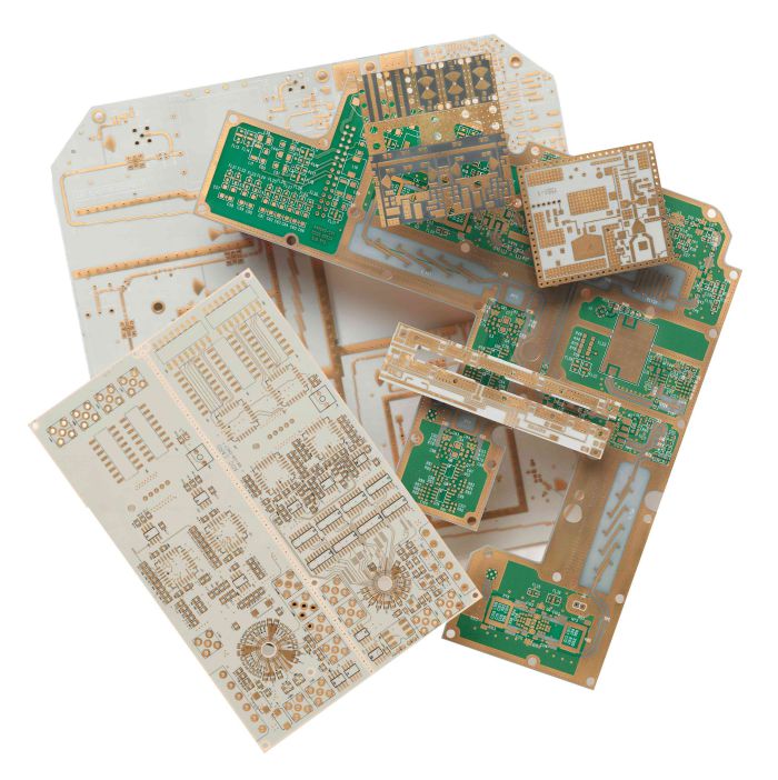
لوحات Rogers PCB هي لوحات دوائر مطبوعة متخصصة مصنوعة من مواد رقائق عالية التردد طورتها شركة Rogers Corporation. تشتهر هذه اللوحات بأدائها الممتاز في إدارة الحرارة والكهرباء، مما يجعلها مفضلة للتطبيقات التي تتطلب سلامة إشارات موثوقة وأداءً عاليًا عند الترددات العالية. وعلى عكس لوحات FR-4 التقليدية، توفر لوحات Rogers خصائص عازلة فائقة، مما يجعلها مثالية للتطبيقات الإلكترونية المتقدمة.
أهميتها في صناعة الإلكترونيات
تُعتبر لوحات Rogers PCB ضرورية في صناعة الإلكترونيات لقدرتها على تلبية متطلبات الأجهزة الحديثة، خاصة تلك التي تعمل في بيئات تتطلب أداءً عاليًا وموثوقية كبيرة. تدعم خصائصها الفريدة تصغير المكونات وتعزيز وظائفها، مما يجعلها لا غنى عنها في إنتاج الإلكترونيات المتطورة. وتكمن هذه الأهمية في قدرتها على التعامل مع الدوائر المعقدة، السرعات العالية، والأداء العام الأفضل مقارنة بمواد اللوحات التقليدية.
التطبيقات في مختلف القطاعات
تُستخدم لوحات Rogers PCB في مجموعة متنوعة من القطاعات، من الاتصالات والطيران إلى السيارات والإلكترونيات الاستهلاكية. في مجال الاتصالات، تسهل نقل البيانات عالي السرعة وبنية تحتية شبكية موثوقة. في الطيران والدفاع، تعتبر لوحات Rogers حيوية لتطوير أنظمة رادار وملاحة متينة وموثوقة. تستفيد صناعة السيارات من أدائها في أنظمة مساعدة السائق المتقدمة وتقنيات المركبات الكهربائية. علاوة على ذلك، تعمل على تحسين أداء الأجهزة الاستهلاكية التي تتطلب إدارة فعالة للحرارة وتشغيلًا عالي التردد. ومع تقدم التكنولوجيا، تتوسع تطبيقات لوحات Rogers PCB، مما يدفع حدود التصميم الإلكتروني إلى آفاق جديدة.
الفصل 2
فهم مواد Rogers
أنواع المواد المستخدمة في لوحات Rogers PCB
تُصنع لوحات Rogers PCB باستخدام مجموعة متنوعة من المواد الرقائقية عالية الأداء التي طورتها شركة Rogers Corporation خصيصًا. تشمل هذه المواد مركبات PTFE (بولي تترافلورو إيثيلين)، السيراميك الهيدروكربوني، وركائز عازلة متخصصة أخرى. تم تصميم كل نوع من المواد لتلبية المتطلبات المحددة لتطبيقات الدوائر عالية التردد. تشمل المواد الشائعة من Rogers سلسلة RT/duroid®، RO4000®، RO3000®، وTMM®، حيث يقدم كل منها خصائص مميزة تناسب متطلبات تقنية وتطبيقات مختلفة.
المقارنة مع المواد التقليدية FR-4
عند مقارنتها بمواد FR-4 التقليدية، توفر مواد Rogers أداءً كهربائيًا وحراريًا فائقًا. يُستخدم FR-4 على نطاق واسع بفضل تكلفته الاقتصادية وتعدد استخداماته في التطبيقات الإلكترونية العادية، لكنه يعاني في سيناريوهات التردد العالي حيث تكون سلامة الإشارة والخصائص العازلة أمرًا بالغ الأهمية. توفر مواد Rogers تقلبًا أقل في ثابت العازل، وخسائر إشارات أقل، ومعامل تمدد حراري أفضل، مما يضمن أداءً مستقرًا حتى عند الترددات العالية. بالإضافة إلى ذلك، تتمتع بقدرات محسنة لإدارة الحرارة، وهي ضرورية لموثوقية وكفاءة الأنظمة الإلكترونية المعقدة.
الفوائد الرئيسية لاستخدام مواد Rogers
- تعزيز سلامة الإشارة: تقلل مواد Rogers من خسائر الإشارة وتضمن موثوقية أكبر في التطبيقات عالية السرعة والتردد.
- إدارة حرارية فائقة: تساعد خصائصها الحرارية الممتازة على تبديد الحرارة بكفاءة، مما يقلل من مخاطر ارتفاع درجة الحرارة ويطيل عمر المكونات الإلكترونية.
- ثبات وموثوقية: بفضل خصائصها العازلة المستقرة عبر نطاق واسع من درجات الحرارة والترددات، توفر مواد Rogers أداءً متوقعًا، وهو أمر بالغ الأهمية للتطبيقات الدقيقة.
- تعدد الاستخدامات في التطبيقات: تتمتع بمرونة كافية للاستخدام في مختلف الصناعات، حيث تقدم حلولًا مخصصة لتلبية احتياجات الاتصالات، الطيران، السيارات، والإلكترونيات الاستهلاكية.
من خلال دمج مواد Rogers في لوحات PCB، يمكن للمصنعين تحقيق الأداء والموثوقية العالية المطلوبة للتطبيقات الإلكترونية المتطورة اليوم، مما يجعلها الخيار المفضل للابتكارات التقنية الرائدة.

الفصل 3

خصائص لوحات Rogers PCB
قدرات إدارة الحرارة
تُعرف لوحات Rogers PCB بقدراتها الاستثنائية في إدارة الحرارة. تستخدم هذه اللوحات مواد عازلة متقدمة تقوم بتبديد الحرارة بفعالية، وهو أمر بالغ الأهمية للحفاظ على أداء ومتانة المكونات الإلكترونية. تضمن الموصلية الحرارية لمواد Rogers نقل الحرارة بسرعة وكفاءة بعيدًا عن العناصر الحساسة للدائرة، مما يقلل من مخاطر الفشل الناتج عن الحرارة. تُعتبر هذه القدرة مفيدة بشكل خاص في التطبيقات التي تتضمن طاقة عالية وترددات عالية، حيث يمكن للمكونات توليد حرارة كبيرة. نتيجة لذلك، تُعد لوحات Rogers PCB مثالية للبيئات التي يكون فيها استقرار درجة الحرارة أمرًا بالغ الأهمية، مثل مضخمات الطاقة وأجهزة الاتصالات ذات التردد العالي.
خصائص الأداء الكهربائي
يُعد الأداء الكهربائي للوحات Rogers PCB من أبرز خصائصها المميزة. فهي تتمتع بثابت عازل منخفض ومعامل فقدان منخفض، مما يقلل من تشوه الإشارة والخسائر في العمليات عالية التردد، مما يؤدي إلى تكامل إشارات فائق. توفر هذه المواد تحكمًا ممتازًا في المعاوقة، وهو أمر ضروري للحفاظ على سلامة الإشارة عند السرعات العالية. بالإضافة إلى ذلك، تتمتع لوحات Rogers PCB بمعامل تمدد حراري منخفض (CTE)، مما يساعد في الحفاظ على أداء كهربائي مستقر عبر نطاق واسع من درجات الحرارة. تجعل هذه الخصائص اللوحات مناسبة للتطبيقات المتقدمة في مجالات الترددات اللاسلكية والميكروويف، حيث لا يمكن المساومة على الدقة والأداء.
المتانة والموثوقية
تقدم لوحات Rogers PCB متانة وموثوقية استثنائية، وهي ضرورية للتطبيقات عالية الأداء والمهمة. توفر قوة مواد Rogers المتأصلة مقاومة للإجهاد الميكانيكي والظروف البيئية مثل الرطوبة والتعرض للمواد الكيميائية. يضمن استقرارها في ظل الظروف الحرارية والكهربائية المتغيرة أداءً متسقًا على مدى فترات طويلة، مما يقلل من احتمالية الفشل وتكاليف الصيانة. تُعتبر هذه الموثوقية حيوية في صناعات مثل الطيران والدفاع، حيث يجب أن تعمل المعدات بشكل لا تشوبه شائبة تحت ظروف قاسية. بشكل عام، تجعل المتانة والموثوقية لوحات Rogers PCB خيارًا مفضلاً لأي تطبيق يتطلب الأداء والاعتمادية على مدار عمر المنتج.
الفصل 4
التصميم باستخدام لوحات Rogers PCB
اعتبارات التصميم وأفضل الممارسات
عند التصميم باستخدام لوحات Rogers PCB، هناك اعتبارات رئيسية وأفضل الممارسات التي يجب اتباعها للاستفادة الكاملة من قدراتها المتقدمة:
- اختيار المواد: يعد اختيار المادة المناسبة من Rogers أمرًا حاسمًا بناءً على التردد المطلوب، المتطلبات الحرارية، وظروف البيئة. تقدم كل مادة خصائص فريدة تؤثر بشكل كبير على الأداء.
- التحكم في المعاوقة: يعد الحفاظ على معاوقة دقيقة أمرًا ضروريًا للتطبيقات عالية التردد. يجب على المصممين تخطيط هندسة ومسافات الخطوط بعناية لضمان معاوقة متسقة في جميع أنحاء التصميم.
- إدارة الحرارة: يساهم دمج تقنيات تبديد الحرارة المناسبة، مثل الفتحات الحرارية، الطبقات النحاسية، والمصارف الحرارية، في تحسين الأداء الحراري وضمان الموثوقية.
- تصميم تكديس الطبقات: يساهم التخطيط الجيد لتكديس الطبقات في تحسين تكامل الإشارة وتقليل مشكلات مثل التداخل والتشويش الكهرومغناطيسي (EMI). يشمل ذلك ترتيب طبقات الإشارة والطاقة والأرضي.
- وضع المكونات والتوجيه: يمكن أن تقلل مواضع المكونات الإستراتيجية والتوجيه الفعال من طول المسارات وتقلل من فقدان أو تأخير الإشارة، وهو أمر ضروري للحفاظ على تكامل الإشارة في الدوائر عالية السرعة.
أدوات البرمجيات لتصميم لوحات Rogers PCB
يتطلب تصميم لوحات Rogers PCB استخدام أدوات برمجية متخصصة للتعامل مع تعقيدات تصميم الدوائر عالية التردد. تشمل الأدوات الشهيرة:
- Altium Designer: يوفر حلولًا شاملة للتصاميم عالية التردد والسرعة، مع ميزات تسهل مطابقة المعاوقة وتحليل تكامل الإشارة.
- Cadence Allegro: معروف بإمكاناته المتقدمة في تصميم RF والميكروويف، حيث يقدم أدوات محاكاة قوية للتنبؤ بالأداء الكهربائي.
- Mentor Graphics Xpedition: يوفر أدوات محاكاة وتحقق قوية تركز على ضمان الأداء الحراري والكهربائي في تصميمات لوحات Rogers PCB.
- ADS (نظام التصميم المتقدم) من Keysight: مصمم خصيصًا لتطبيقات RF، الميكروويف، والرقمية عالية السرعة، مما يتيح نمذجة دقيقة والتحقق من الدوائر المعقدة.
تحديات تصميم لوحات Rogers PCB
رغم المزايا، فإن تصميم لوحات Rogers PCB يواجه عدة تحديات:
- تعقيد التعامل مع المواد: تتطلب الخصائص الفريدة لمواد Rogers تعاملًا دقيقًا أثناء عملية التصنيع لتجنب العيوب وضمان الأداء.
- اعتبارات التكلفة: يمكن أن تكون مواد Rogers مكلفة بشكل كبير مقارنة بمواد FR-4 التقليدية، مما يستدعي تحليلًا دقيقًا للتكلفة والفائدة، خصوصًا للإنتاج واسع النطاق.
- القيود الحرارية والميكانيكية: يجب على المصممين إدارة القيود الحرارية والميكانيكية بعناية لمنع الالتواء أو الانفصال الطبقي الذي قد يحدث بسبب اختلاف خواص التمدد الحراري للمواد.
- الدقة في التصميم عالي التردد: يتطلب تحقيق التحكم الدقيق في المعاوقة وتقليل EMI في البيئات عالية التردد خبرة تصميم متقدمة واهتمامًا دقيقًا بالتفاصيل.
رغم هذه التحديات، فإن الالتزام بأفضل الممارسات والاستفادة من أدوات التصميم المتخصصة يمكن أن يساعد في التغلب على العقبات وتحقيق أقصى استفادة من لوحات Rogers PCB في التطبيقات الإلكترونية المعقدة.

الفصل 5

عمليات تصنيع لوحات Rogers PCB
الخطوات الرئيسية في عملية التصنيع
يتطلب تصنيع لوحات Rogers PCB سلسلة من الخطوات الدقيقة والمنضبطة لضمان إنتاج لوحات عالية الجودة تلبي متطلبات الأداء المتخصصة:
- تحضير المواد: تبدأ العملية باختيار المادة الرقائقية المناسبة من Rogers بناءً على المواصفات التصميمية. يتم تجهيز الأوراق وتنظيفها بعناية لإزالة أي ملوثات قد تؤثر على الالتصاق والأداء.
- نقل الصورة: يتم نقل تصميم اللوحة إلى الرقاقة النحاسية باستخدام تقنية الطباعة الضوئية. يشمل ذلك تطبيق فيلم حساس للضوء (photoresist)، ثم تعريضه للأشعة فوق البنفسجية من خلال قناع فوتوغرافي لتصميم اللوحة، ثم تطوير الصورة.
- النقش: يتم نقش النحاس المكشوف لإزالة المناطق غير المرغوب فيها، مع ترك أنماط الدائرة المطلوبة فقط. يجب التحكم بدقة في هذه الخطوة لضمان دقة الأبعاد وتجنب النقش الزائد أو الناقص.
- الحفر والتغليف: تُحفر فتحات الفيا والمكونات عبر الثقوب باستخدام آلات CNC دقيقة. يتم بعد ذلك تغليف الفتحات المحفورة لضمان الاتصال الكهربائي بين طبقات PCB.
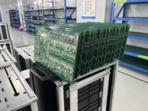
- التصفيف: بالنسبة للوحات متعددة الطبقات، يتم تكديس الطبقات الفردية وتصفيحها تحت الحرارة والضغط لتشكيل هيكل موحد. تُعد هذه الخطوة حاسمة لضمان الاستقرار الميكانيكي والمحاذاة.
- إنهاء السطح: يتم تطبيق تشطيب السطح لحماية النحاس المكشوف وتوفير سطح قابل للحام. تشمل التشطيبات الشائعة HASL (تسوية اللحام بالهواء الساخن)، ENIG (النيكل غير الكهربائي والغمر الذهبي)، وتشطيبات أخرى مخصصة لتطبيقات محددة.
- قناع اللحام والطباعة: يتم تطبيق قناع اللحام لمنع الجسور اللحامية بين المسارات الموصلة. تُستخدم الطباعة لإضافة تسميات المكونات ومُعرفات أخرى إلى اللوحة.
التقنيات والأساليب المستخدمة
يتضمن تصنيع لوحات Rogers PCB تقنيات وأساليب متقدمة:
- الحفر باستخدام CNC الدقيق: يضمن وضع الفتحات بدقة وأحجامها المثالية، وهو أمر بالغ الأهمية للأداء في التطبيقات عالية التردد.
- تصوير الليزر المباشر (LDI): يُستخدم في نقل الصور لأنماط PCB الدقيقة، مما يوفر دقة أكبر مقارنة بالطرق التقليدية للطباعة الضوئية.
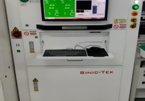
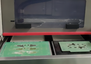
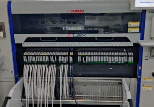
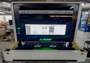
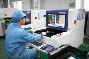
- الفحص البصري الآلي (AOI): تستخدم الأنظمة كاميرات عالية الدقة وخوارزميات لفحص اللوحة بحثًا عن العيوب أثناء مراحل التصنيع المختلفة، مما يضمن الجودة والاتساق.
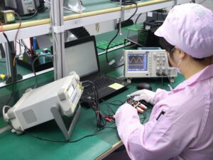
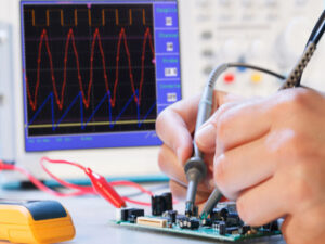
- معدات اختبار التردد العالي: تُستخدم لتقييم الأداء الكهربائي أثناء التصنيع لضمان مطابقة اللوحة لمتطلبات التردد العالي المحددة.
إجراءات مراقبة الجودة
تخضع لوحات Rogers PCB لإجراءات صارمة لمراقبة الجودة لضمان مطابقتها للمعايير الصارمة اللازمة لتطبيقاتها المتخصصة:
- التحقق من المواد: قبل الإنتاج، يتم فحص المواد والتحقق من توافقها مع التطبيقات المقصودة، مع التركيز على الخصائص العازلة والأبعاد الفيزيائية.
- الدقة الأبعادية: تُقاس الطبقات والمسارات باستخدام أدوات قياس عالية الدقة للتحقق من مطابقتها للمواصفات التصميمية، وتجنب أي انحرافات قد تؤثر على الأداء.
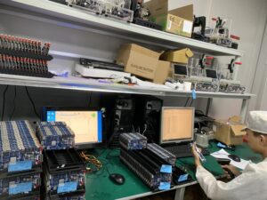
- الاختبارات الكهربائية: تخضع كل لوحة لاختبارات كهربائية للتأكد من الاستمرارية، المعاوقة، ومقاومة العزل، مما يثبت أن اللوحة تعمل بشكل صحيح تحت ظروف التشغيل.
- اختبار الإجهاد الحراري: يتم اختبار اللوحات لتحمل الدورات الحرارية التي قد تواجهها في بيئاتها التشغيلية دون تدهور.
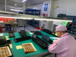
- الفحص النهائي: يُجرى فحص نهائي شامل، غالبًا بتعاون بين الإنسان والآلات، للتأكد من خلو اللوحات من العيوب البصرية ومطابقتها لجميع معايير الجودة المحددة قبل التسليم.
من خلال الحفاظ على رقابة صارمة في كل مرحلة من مراحل عملية التصنيع، يتم إنتاج لوحات Rogers PCB بالموثوقية والأداء المطلوبين للتطبيقات التي تتطلب الترددات العالية والطاقة العالية.
الفصل 6
تطبيقات لوحات Rogers PCB
حالات الاستخدام في صناعات الاتصالات، الطيران، والسيارات
تُعتبر لوحات Rogers PCB خيارًا بارزًا في العديد من القطاعات الصناعية بفضل قدرتها على تلبية المتطلبات الإلكترونية المعقدة بكفاءة:
الاتصالات: تُستخدم لوحات Rogers PCB على نطاق واسع في مكونات RF والميكروويف مثل الهوائيات، المكبرات، وأجهزة الإرسال. تجعل خصائصها العازلة الممتازة وقدراتها العالية في إدارة الحرارة مثالية للحفاظ على سلامة الإشارة وتقليل الفاقد في أنظمة الاتصالات ذات التردد العالي.
الطيران: يتطلب قطاع الطيران مواد قادرة على تحمل الظروف القاسية مثل درجات الحرارة العالية، الرطوبة، والاهتزازات. تلبي لوحات Rogers PCB هذه التحديات بفضل متانتها العالية وموثوقيتها. تُستخدم في أنظمة الرادار، المستشعرات الجوية، والاتصالات بالأقمار الصناعية، حيث تكون الدقة في الأداء أمرًا بالغ الأهمية.
السيارات: مع تقدم صناعة السيارات، خاصةً مع تطوير المركبات الكهربائية وتقنيات القيادة الذاتية، تزايد الطلب على الأنظمة الإلكترونية عالية الأداء. تُستخدم لوحات Rogers PCB في أنظمة الرادار والمستشعرات، أنظمة إدارة الطاقة، وأنظمة الترفيه والمعلومات بفضل استقرارها تحت ظروف متغيرة وأدائها الكهربائي الممتاز.
الفوائد في التطبيقات عالية التردد
تتميز لوحات Rogers PCB بخصائص مادية متخصصة تجعلها مثالية للتطبيقات عالية التردد:
خسارة عازلة منخفضة: تقدم الحد الأدنى من الخسائر العازلة، وهو أمر ضروري للحفاظ على وضوح الإشارة وقوتها في العمليات ذات التردد العالي، مما يقلل من التشويه أو التوهين.
ثابت عازل متسق: يضمن الثابت العازل المستقر عبر نطاق واسع من الترددات ودرجات الحرارة أداءً كهربائيًا متوقعًا، وهو مطلب أساسي في تطبيقات RF والميكروويف المتقدمة.
قدرات عالية في تحمل الطاقة: يمكن للمواد المستخدمة في لوحات Rogers PCB تبديد الحرارة بكفاءة، مما يسمح لها بتحمل مستويات طاقة عالية دون التأثير على الأداء، مما يجعلها مناسبة للاستخدام في تطبيقات RF ذات الطاقة العالية.
التطبيقات الناشئة والاتجاهات
مع تقدم التكنولوجيا، تتصدر لوحات Rogers PCB العديد من التطبيقات الناشئة والاتجاهات:
تقنية الجيل الخامس (5G): يتطلب انتشار شبكات 5G مكونات يمكنها العمل بترددات أعلى وكفاءة أكبر. تُستخدم لوحات Rogers PCB بشكل متزايد في تطوير بنية تحتية 5G، بما في ذلك محطات القاعدة والخلايا الصغيرة، حيث الأداء العالي عند الترددات المليمترية أمر ضروري.
إنترنت الأشياء والأجهزة القابلة للارتداء: مع توسع إنترنت الأشياء وزيادة الطلب على الأجهزة المدمجة والفعالة، تُستخدم لوحات Rogers PCB في المستشعرات المصغرة ووحدات الاتصال، بفضل وزنها الخفيف وأدائها المتميز.
الإلكترونيات المتقدمة للسيارات: مع تزايد ذكاء المركبات واستخدام أنظمة إلكترونية معقدة للقيادة الذاتية، أنظمة مساعدة السائق المتقدمة (ADAS)، وأنظمة الاتصال بين المركبات، توفر لوحات Rogers PCB الموثوقية والدقة اللازمتين.
التطبيقات العسكرية والدفاعية: الحاجة إلى الإلكترونيات المتطورة في الحروب الحديثة دفعت استخدام لوحات Rogers PCB في أجهزة الاتصال العسكرية، الرادار، وأنظمة التوجيه، حيث الاستقرار البيئي والأداء القوي أمران حاسمان.
الخلاصة
تُظهر التطبيقات المتنوعة للوحات Rogers PCB في الصناعات التقنية المتقدمة قدراتها الفريدة، مما يجعلها حجر الزاوية للتقدم التكنولوجي الحالي والمستقبلي.

الفصل 7

مقارنة لوحات Rogers PCB مع أنواع أخرى من اللوحات المطبوعة
الاختلافات والتشابهات مع لوحات PCB الأخرى
تختلف لوحات Rogers PCB عن اللوحات التقليدية، مثل تلك المصنوعة من مادة FR-4، في العديد من الجوانب:
الخصائص العازلة: توفر لوحات Rogers PCB ثابت عازل منخفض (DK) ومعامل فقدان أقل مقارنةً بـ FR-4، مما يعزز الأداء في التطبيقات عالية التردد. يؤدي ذلك إلى تحسين تكامل الإشارة وتقليل الخسائر.
إدارة الحرارة: تتميز مواد Rogers بموصلية حرارية فائقة، مما يسمح لها بتبديد الحرارة بفعالية أكبر مقارنةً بلوحات FR-4 التقليدية، وهو أمر حيوي للتطبيقات ذات المتطلبات الحرارية الكبيرة.
تركيب المواد: تتكون لوحات Rogers PCB من رقائق سيراميكية هيدروكربونية، مما يوفر استقرارًا ميكانيكيًا وأداءً كهربائيًا أفضل، بينما تتكون FR-4 من زجاج منسوج وراتنج إيبوكسي.
الثبات البيئي: تقدم مواد Rogers استقرارًا أكبر عبر نطاق واسع من درجات الحرارة وظروف البيئة، مما يجعلها مناسبة للبيئات القاسية.
الإيجابيات والسلبيات مقارنة باللوحات التقليدية
الإيجابيات:
- الأداء العالي التردد: تتميز لوحات Rogers PCB بقدرتها على الأداء بشكل استثنائي عند الترددات العالية، مما يجعلها مثالية لتطبيقات RF والميكروويف.
- الصلابة الحرارية والميكانيكية: توفر إدارة حرارية ممتازة واستقرارًا ميكانيكيًا، مما يزيد من عمر المكونات الإلكترونية.
- خسارة إشارة منخفضة: تحسين وضوح الإشارة وقوتها، وتقليل التشويه والتداخل.
- مرونة التصميم: تدعم المواد تصميمات معقدة، مما يتيح تكوينات متعددة الطبقات لتطبيقات متقدمة.
السلبيات:
- التكلفة العالية: تُعد لوحات Rogers PCB أكثر تكلفة مقارنةً بلوحات FR-4 التقليدية بسبب المواد المتخصصة وعملية التصنيع.
- متطلبات التصنيع المعقدة: تحتاج عمليات التصنيع الدقيقة للـ Rogers PCB إلى معدات وخبرات متخصصة.
تكاليف التصنيع ومزايا الأداء
تُعد تكاليف استخدام لوحات Rogers PCB كبيرة بسبب ارتفاع سعر المواد الخام وتقنيات التصنيع المتخصصة. ومع ذلك، يمكن تبرير هذه التكاليف في الحالات التي تكون فيها مكاسب الأداء ضرورية:
- مزايا الأداء: تقدم لوحات Rogers PCB أداءً لا مثيل له في التطبيقات التي تتطلب تشغيلًا عالي التردد، وتحكمًا دقيقًا في المعاوقة، وموثوقية حرارية، وهو ما لا يمكن تحقيقه باستخدام اللوحات القياسية.
- القيمة على المدى الطويل: بالرغم من التكلفة الأولية المرتفعة، فإن الموثوقية العالية وطول عمر لوحات Rogers PCB يمكن أن يؤديان إلى تقليل تكاليف الصيانة والاستبدال على مدار دورة حياة المنتج.
- تحليل التكلفة والفائدة: في التطبيقات التي تفوق فيها مزايا الأداء والموثوقية التكلفة، تقدم لوحات Rogers PCB فوائد كبيرة. تعتبر صناعات مثل الاتصالات، الطيران، والدفاع هذه اللوحات استثمارًا في الجودة والموثوقية.
الخلاصة
بينما تُعد لوحات Rogers PCB أكثر تكلفة مقارنة بأنواع اللوحات التقليدية، فإن قدراتها المتخصصة تجعلها لا غنى عنها في التطبيقات عالية الأداء التي تتطلب دقة، متانة، وموثوقية عالية.
الفصل 8
استكشاف المشكلات الشائعة وحلها مع لوحات Rogers PCB
تحديد ومعالجة المشكلات الشائعة
على الرغم من القدرات المتقدمة للوحات Rogers PCB، قد يواجه المصممون والمهندسون مشكلات مختلفة أثناء التصميم أو التصنيع أو الاستخدام. فهم هذه المشكلات ومعالجتها أمر ضروري للحفاظ على أداء وموثوقية اللوحات:
تفاوت المعاوقة: يمكن أن يؤدي التفاوت في المعاوقة إلى مشكلات في سلامة الإشارة، خاصةً في التطبيقات عالية التردد.
الحل: ضمان التحكم الدقيق في عرض المسارات والمسافات خلال مرحلة التصميم. قم بمعايرة معدات التصنيع بانتظام للحفاظ على التناسق، واستخدم أدوات المحاكاة للتنبؤ بمشكلات المعاوقة.الانفصال الطبقي: قد يحدث إذا تعرضت اللوحة لإجهاد حراري غير مناسب أو إذا كانت هناك فجوات في الطبقات.
الحل: الانتباه إلى الملفات الحرارية أثناء التصنيع. تأكد من أن عملية التصفيح يتم التحكم فيها بعناية مع إعدادات الضغط ودرجة الحرارة المناسبة لتجنب الانفصال.فشل الفتحات: يمكن أن يؤدي الإجهاد الحراري والتردد العالي إلى فشل الفتحات.
الحل: استخدام فتحات مملوءة ومغطاة لتحسين الاستقرار الميكانيكي والأداء الحراري. اختيار هياكل الفتحات داخل اللوحة لتقليل الحث وتعزيز تبديد الحرارة.مشكلات اللحام: قد تنشأ من التشطيبات السطحية الرديئة أو التلوث على سطح اللوحة.
الحل: استخدام تشطيبات سطحية عالية الجودة مثل ENIG أو الفضة الغامرة. ضمان تنظيف شامل ومعالجة سليمة أثناء عملية التصنيع لتجنب التلوث.
نصائح لضمان الأداء الأمثل
- دقة التصميم: استخدام أدوات تصميم PCB المتقدمة التي توفر تحليلات مفصلة للتخطيطات عالية التردد. الاستفادة من محاكاة ثلاثية الأبعاد (3D EM) للتنبؤ بأداء اللوحة بدقة أكبر.
- فحوصات سلامة الإشارة: إجراء تحليلات منتظمة لسلامة الإشارة، خاصة عند إجراء تغييرات على التصميم، لضمان توافق اللوحة مع مواصفات الأداء.
- إدارة الحرارة: تطبيق استراتيجيات فعالة لإدارة الحرارة مثل المصارف الحرارية، الفتحات الحرارية، وصب النحاس لتوزيع الحرارة بفعالية.
- اختيار المكونات: اختيار مكونات متوافقة مع العمليات عالية التردد وقادرة على تحمل الإجهادات الحرارية والميكانيكية لتطبيقك.
استراتيجيات الصيانة والإصلاح
الحفاظ على سلامة لوحات Rogers PCB بمرور الوقت يتطلب اتخاذ تدابير وقائية وتصحيحية:
- الفحوصات المنتظمة: إجراء فحوصات بصرية ووظيفية لتحديد علامات التآكل أو الانفصال الطبقي أو الأضرار الحرارية مبكرًا. استخدام أدوات فحص بصرية وأشعة سينية لتحليل شامل.
- التحكم البيئي: تخزين وتشغيل اللوحات في بيئات تتوافق مع درجات الحرارة ونطاقات الرطوبة المحددة لمنع امتصاص الرطوبة ومشكلات التمدد الحراري.
- الإصلاحات: يمكن تنفيذ إعادة العمل بعناية للوحات التالفة بواسطة فنيين مدربين. قد يشمل ذلك إصلاح المسارات التالفة، استبدال المكونات الفاشلة، أو حتى ترقيع مناطق معينة بمواد نحاسية أو عازلة جديدة.
- التنظيف: استخدام عوامل تنظيف مناسبة لا تترك رواسب وضمان خلو اللوحات من الغبار والحطام، مما قد يسبب دوائر قصر أو يؤثر على الأداء.
الخلاصة
من خلال معالجة هذه التحديات بشكل استباقي وتنفيذ استراتيجيات صارمة لمراقبة الجودة والصيانة، يمكن للمهندسين تحسين موثوقية ووظائف لوحات Rogers PCB بشكل كبير في تطبيقاتهم.

الفصل 9
الاتجاهات المستقبلية في لوحات Rogers PCB
الابتكارات والتطورات في المواد والتصميم
يتشكل مستقبل لوحات Rogers PCB من خلال الابتكارات المستمرة في المواد وتقنيات التصميم، لتلبية احتياجات التطبيقات عالية التردد والأداء المتطور:
تطوير المواد المتقدمة: من المتوقع أن تقدم مواد Rogers المستقبلية ثابت عازل أقل ومعامل فقدان منخفض، مما يعزز الأداء في الترددات العالية. قد تؤدي التطورات في المواد المركبة والنانوية إلى رقائق ذات خصائص حرارية وقوة ميكانيكية محسنة.
التصغير والدمج: مع استمرار تقلص الأجهزة الإلكترونية، ستشهد لوحات Rogers PCB تقدمًا في التصغير، مما يتيح تصاميم أكثر إحكامًا مع مكونات مدمجة. ستصبح الابتكارات مثل المكونات السلبية المدمجة وتقنيات النظام في الحزمة (SiP) أكثر انتشارًا.
حلول محسّنة لإدارة الحرارة: سيكون دمج مواد وتصاميم جديدة تركز على تبديد الحرارة أولوية لدعم الأجهزة الإلكترونية التي تعمل بكثافة طاقة أعلى دون التأثير على الموثوقية.
تأثير التقنيات الناشئة
من المتوقع أن تؤثر التقنيات الناشئة بشكل كبير على تطوير واستخدام لوحات Rogers PCB:
تقنية الجيل الخامس وما بعدها: مع تسارع اعتماد شبكات 5G عالميًا والبدء في وضع الأسس للجيل السادس (6G)، ستكون لوحات Rogers PCB أساسية في دعم البنية التحتية والأجهزة التي تعمل بترددات أعلى بشكل متزايد.
التطورات في صناعة السيارات: يتطلب صعود المركبات الكهربائية والمستقلة أنظمة إلكترونية متقدمة تناسبها لوحات Rogers PCB، بما في ذلك أنظمة الرادار والليدار، بالإضافة إلى حلول إدارة الطاقة والاتصال.
توسع إنترنت الأشياء (IoT): سيؤدي نمو تطبيقات إنترنت الأشياء إلى زيادة الطلب على لوحات PCB التي يمكنها توفير اتصالات طويلة المدى وموثوقة في أشكال مضغوطة. ستلعب لوحات Rogers PCB دورًا حيويًا في توفير الخصائص اللازمة للأداء.
واجهات الذكاء الاصطناعي والتعلم الآلي: تتطلب الأجهزة المدفوعة بالذكاء الاصطناعي معالجة متقدمة واتصالاً موثوقًا، مما يخلق طلبًا على لوحات PCB قادرة على إدارة تدفقات بيانات معقدة ومعالجة في الوقت الفعلي، وهي مجالات تتميز فيها لوحات Rogers PCB.
توقعات نمو السوق والطلب
من المتوقع أن يزداد الطلب على لوحات Rogers PCB بشكل كبير في السنوات القادمة، مدفوعًا بعدة عوامل:
زيادة الاعتماد في الاتصالات والطيران: ستستمر الاستثمارات في البنية التحتية للاتصالات والابتكارات في الطيران في دعم الطلب على لوحات PCB عالية الأداء القادرة على العمل في ظل ظروف صارمة.
توسع سوق السيارات: مع تكامل المركبات الحديثة لأنظمة إلكترونية أكثر تعقيدًا، سيزداد الطلب على لوحات PCB القادرة على التعامل مع الترددات العالية والأداء الكهربائي المتين.
نمو الإلكترونيات الاستهلاكية: ستساهم الابتكارات في الإلكترونيات الاستهلاكية التي تتطلب اتصالًا فعالًا وعالي السرعة في زيادة استخدام لوحات Rogers PCB.
التوسع في السوق العالمي: مع تسارع التطور التكنولوجي دوليًا، خصوصًا في المناطق التي تركز على التقدم الصناعي (مثل آسيا والمحيط الهادئ)، يتوقع أن يشهد سوق لوحات Rogers PCB توسعًا كبيرًا.
الخلاصة
يبدو مستقبل لوحات Rogers PCB واعدًا، حيث تقود الابتكارات التكنولوجية دمجها في مجموعة متزايدة من التطبيقات. مع استمرار الصناعات في توسيع حدود ما يمكن تحقيقه بالإلكترونيات عالية التردد، ستظل لوحات Rogers PCB حجر الزاوية في الابتكار والتطوير.
الفصل 10
اختيار المورد المناسب للوحات Rogers PCB
معايير اختيار مورد موثوق
اختيار المورد المناسب للوحات Rogers PCB أمر بالغ الأهمية لضمان الجودة، الأداء، والموثوقية للمنتج النهائي. إليك بعض المعايير الرئيسية التي يجب مراعاتها:
- الخبرة والتجربة: ابحث عن موردين لديهم خبرة واسعة في تصنيع لوحات Rogers PCB. يعد السجل الحافل في التعامل مع المواد عالية التردد والمواد المتقدمة أمرًا ضروريًا.
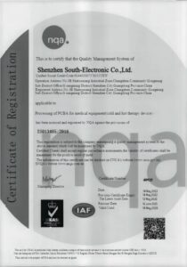
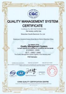
- عمليات ضمان الجودة: تأكد من أن المورد يتبع إجراءات صارمة لمراقبة الجودة ويتوافق مع معايير وشهادات الصناعة (مثل ISO 9001 ومعايير IPC).
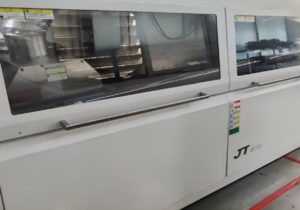
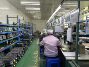
- المرافق المتطورة: تُعد المنشآت التصنيعية المتقدمة والمجهزة بأحدث التقنيات والأدوات ضرورية لإنتاج لوحات PCB عالية الجودة.
- قدرات التخصيص: يجب أن يقدم المورد مرونة في التخصيص لتلبية متطلبات التصميم المحددة واستيعاب لوحات PCB متعددة الطبقات المعقدة.
- الدعم الفني والتعاون: يمكن أن يعزز المورد الذي يقدم دعمًا فنيًا ممتازًا ومستعد للتعاون الوثيق خلال عمليات التصميم والتصنيع من جودة المنتج النهائي بشكل كبير.
دراسات حالة لتطبيقات ناجحة
فيما يلي أمثلة لبعض التطبيقات الناجحة للوحات Rogers PCB من قبل شركات كبرى أو في تطبيقات محددة:
شركة البنية التحتية للاتصالات: تعاونت شركة رائدة في مجال الاتصالات مع مصنع لوحات PCB متخصص في مواد Rogers لتطوير لوحات دوائر متقدمة عالية التردد لبنية شبكتها 5G. ساهمت اللوحات، المصممة لتحقيق تكامل إشارات مثالي وإدارة حرارية فعالة، في تعزيز موثوقية وأداء الشبكة، مما أدى إلى تحديد معيار جديد في نشر شبكات 5G.
مقاول دفاعي في مجال الطيران: احتاجت شركة طيران كبرى إلى لوحات PCB متينة لأنظمة الرادار والاتصالات المستخدمة في التطبيقات العسكرية. من خلال التعاون مع مورد ذو خبرة في لوحات Rogers PCB، نجحوا في تنفيذ لوحات متعددة الطبقات ذات تصميمات معقدة تتحمل الظروف البيئية القاسية، مما أدى إلى تحسين موثوقية النظام ونجاح المهام.
الخلاصة
توضح هذه الدراسات أهمية اختيار مورد ذو كفاءة وخبرة محددة في لوحات Rogers PCB لتحقيق نتائج مثالية في التطبيقات الصعبة. من خلال التقييم الدقيق للموردين المحتملين بناءً على خبرتهم وقدراتهم وخدمات الدعم التي يقدمونها، يمكن للشركات ضمان استفادة مشاريعها من لوحات PCB عالية الجودة والأداء.

تواصل معنا
أين نحن؟
الحديقة الصناعية، رقم 438 شارع دونغ هوان، رقم 438، شاجينغ دونغ هوان، منطقة باوان، شنتشن، قوانغدونغ، الصين
الطابق 4، مبنى زهيهوي الإبداعي، رقم 2005 شارع شيهوان، شاجينغ، منطقة باوان، شنتشن، الصين
الغرفة A1-13، الطابق 3، مركز يي ليم الصناعي، 2-28 شارع كواي لوك، كواي تشونغ، هونغ كونغ
service@southelectronicpcb.com
الهاتف: +86 400 878 3488
أرسل لنا رسالة
كلما كانت التفاصيل أكثر دقة، كلما تمكنا من المضي قدمًا إلى الخطوة التالية أسرع.


