Printed Circuit Boards (PCBs) are integral components in nearly every modern electronic device. While they are typically viewed as platforms for mounting and interconnecting components, PCBs themselves can also exhibit electrical properties. One of these properties is capacitance, which raises the question: Can a PCB itself behave as a capacitor?
Understanding Capacitance in PCBs
At its core, capacitance is the ability of a system to store an electrical charge. In a typical capacitor, two conductive plates are separated by an insulating material (dielectric). When voltage is applied, the electric field generated stores energy. Similarly, in a PCB, certain layers and traces can form a parallel plate structure, thus exhibiting capacitive behavior.
How Can a PCB Behave Like a Capacitor?
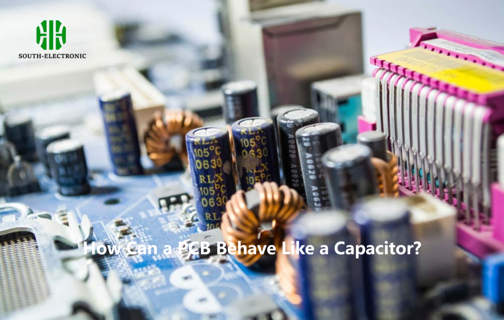
The physical structure of a PCB can cause it to behave as a capacitor, particularly in multilayer PCBs where ground planes and power planes are separated by a dielectric material, typically FR4. This layered structure acts similarly to a traditional capacitor, with the PCB’s copper layers as the plates and the dielectric material acting as the insulating layer.
Key Mechanisms for PCB Capacitance:
- Plane Capacitance: Ground and power planes act as parallel plates.
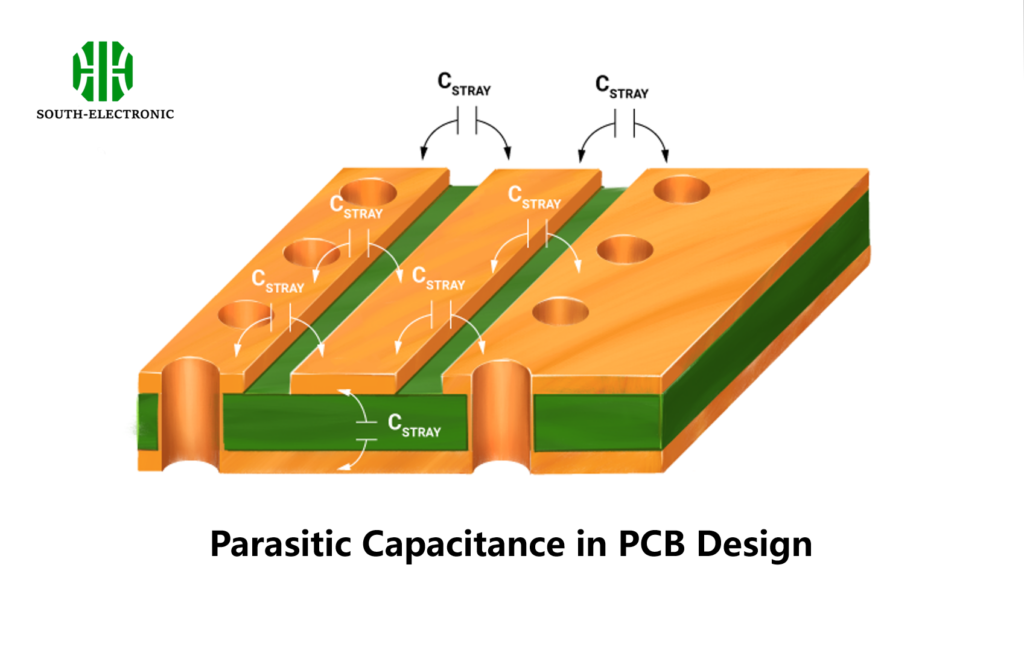
- Trace-to-Trace Capacitance: PCB traces running close to each other also create parasitic capacitance.
- Via Capacitance: Vias connecting layers can introduce small but measurable capacitance.
Factors Affecting PCB Capacitance:
- Dielectric Material: The choice of dielectric affects the capacitance. For example, FR4 has a dielectric constant around 4.5.
- Layer Spacing: Reducing the distance between layers increases capacitance.
- Trace Geometry: Wider traces or planes increase capacitance.
Practical Applications of PCB Capacitance

Decoupling Capacitors and Embedded Capacitance
In high-speed circuits, PCB capacitance can be intentionally used to improve circuit performance by providing local decoupling capacitance between the ground and power planes. This helps reduce noise and maintain signal integrity. This concept, known as embedded capacitance, is particularly useful in reducing the number of discrete capacitors required.
Advantages and Disadvantages of Embedded Capacitance in PCBs
| Advantages | Disadvantages |
|---|---|
| Reduced need for discrete capacitors | Requires careful PCB design to optimize capacitance |
| Enhanced signal integrity | Limited by material properties |
| Reduces board space and component cost | Higher manufacturing complexity |
| Improved high-frequency performance | Increased PCB cost due to added layers |
Can a Wire Act as a Capacitor?
Interestingly, even wires exhibit capacitive behavior. Every cable exhibits some capacitance, and in certain applications, it is essential to minimize this capacitance to avoid undesired effects, especially in high-frequency circuits.
Now, bearing in mind that every cable exhibits some capacitance, and therefore behaves a bit like our makeshift capacitor, it’s evident why you would want to minimize capacitance in a cable.
Parasitic Capacitance in PCB Design
One of the main challenges of designing PCBs is dealing with parasitic capacitance. Parasitic capacitance refers to the unintended capacitance that occurs between PCB traces, components, and vias. This capacitance can cause issues like signal degradation, especially in high-speed circuits.
How to Reduce Parasitic Capacitance
- Increase Trace Spacing: Keeping traces far apart reduces parasitic capacitance.
- Use Low-Dielectric Materials: Materials with lower dielectric constants, such as Rogers 4000 series, can help minimize unwanted capacitance.
- Shielding Sensitive Signals: Use ground planes to shield sensitive signal traces from nearby noise sources.
Capacitance of FR4 PCB
FR4 is the most commonly used dielectric material in PCB manufacturing. It is a composite material made of woven fiberglass cloth with an epoxy resin binder that is flame resistant.
Typical Capacitance of FR4 Material
The dielectric constant (Er) of FR4 is typically around 4.5, and the capacitance between traces or planes depends on the thickness of the dielectric layer.
Capacitance of FR4 PCB at Different Thicknesses
| Layer Thickness (mm) | Capacitance (pF) |
|---|---|
| 0.2 mm | 2.2 pF |
| 0.4 mm | 1.1 pF |
| 0.6 mm | 0.7 pF |
| 0.8 mm | 0.5 pF |
Conclusion
Yes, a PCB can behave as a capacitor, and this can be good or bad depending on the design and application. By understanding how capacitance works in a PCB, designers can either use it to their advantage or minimize its impact in high-speed circuits.
As we’ve seen, things like the type of dielectric material, trace spacing, and layer configuration all play a role in determining the capacitance of a PCB. Whether through embedded capacitance or parasitic effects, the capacitance of a PCB is a fundamental aspect of its electrical performance and can have a big impact on the final product.


