
Ever wondered how flexible electronics get their complex circuits? Double-sided FPC manufacturing holds the key.
The main processes include material cutting, drilling, hole metallization, surface cleaning, and resist coating for precise circuit formation.
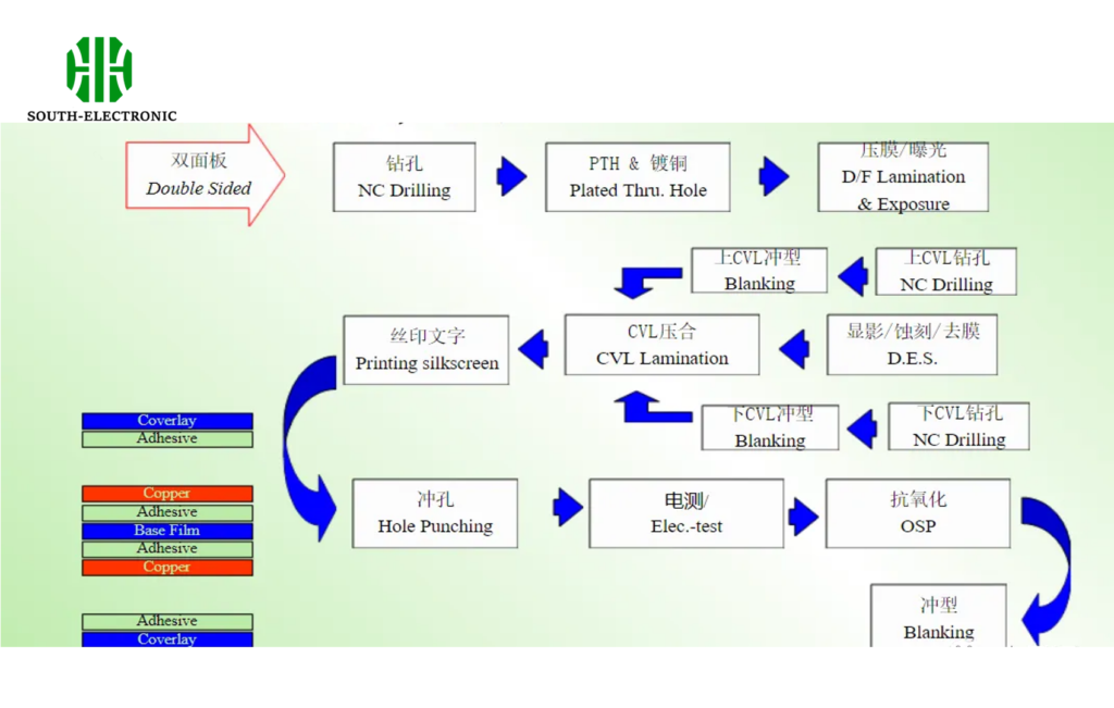
Let me walk you through each step to understand why each is crucial and how they contribute to the final product’s reliability.
FPC Material Cutting?
Starting with material cutting might seem basic, but it’s make-or-break for FPC quality. I once saw a batch ruined by improper cutting.
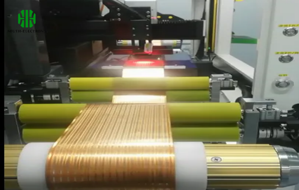
Double-sided FPC begins with cutting flexible copper-clad laminates, using manual shears for small batches or automatic cutters for large runs.
Firstly, the material is delicate—even a small scratch can cause failures later. For small quantities, I’ve used hand-held shearers or roller cutters, which work but need careful handling. For mass production, automatic cutters are a must. These machines can achieve ±0.33mm precision, stacking materials neatly without wrinkles. Newer models even use optical sensors to align cuts to etched patterns, though the borders can’t be used for later positioning. Here’s a breakdown:
| Cutting Method | Precision | Suitable for | Key Advantages |
|---|---|---|---|
| Manual Shears | ±0.5mm | Small batches | Low cost, portable |
| Automatic Cutter | ±0.33mm | Large batches | High speed, minimal damage |
| Optical-guided Cutter | ±0.3mm | Pre-etched materials | Pattern-based alignment |
I remember a project where we tried using a standard cutter on thin laminates—it caused too much stretching. Switching to a roller-fed model solved the issue instantly.
Drilling Through-Holes for Double-Sided FPC?
Drilling tiny holes in flexible boards sounds tricky—and it is. I’ve seen teams struggle with choosing the right drilling method.
Common drilling methods include CNC drilling, punching, and laser drilling, each suited for different hole sizes and volumes.
CNC drilling is still widely used, but it has limits. I once overlapped 10 sheets and drilled with an aluminum backing plate, which worked well for 0.5mm holes. But for smaller holes, new tech shines. Laser drilling, like excimer lasers, can make 10-20μm holes, though carbon residue is an issue. Punching has come a long way—new molds can punch 75μm holes in 25μm substrates. Here’s a comparison:
| Drilling Method | Min Hole Size | Speed | Cost | Best For |
|---|---|---|---|---|
| CNC Drilling | 0.3mm | Medium | Low | Medium batches, larger holes |
| Punching | 50μm | High | High | Mass production, uniform holes |
| Excimer Laser | 10μm | Low | Very high | Micro-holes, high precision |
| CO2 Laser | 70μm | Medium | High | Insulation-only holes |
Laser drilling’s biggest challenge is cost, but for TAB processes, its speed in narrow widths is unbeatable. I recall a project where we needed 80μm holes—CO2 laser was too slow, so we switched to punching and saved weeks.
How Is Hole Metallization Done for Double-Sided FPC?
Hole metallization connects both sides, but flexible boards need special care. I once had a batch with uneven plating—nightmare to fix.
Hole metallization uses similar processes to rigid PCBs, with direct plating replacing chemical plating in some cases.
The key is fixing the flexible board securely. I’ve used custom fixtures to keep the board taut, otherwise plating thickness varies. Direct plating (carbon layer) is gaining ground—it’s faster and eco-friendlier. When outsourcing, check if the factory has flexible PCB experience. Once, we sent boards to a rigid PCB shop, and they used standard fixtures—results were disastrous. Here’s a step-by-step look:
- Pre-treatment: Clean holes to remove debris.
- Activation: Catalyze holes for plating.
- Plating: Electroless copper to coat holes, followed by electrolytic plating.
- Inspection: Check for voids or thin plating.
Fixtures matter: we now use tensioned frames with adjustable electrodes. Also, never skip the pre-treatment—even a tiny residue causes opens.
Why Is Copper Surface Cleaning Critical in FPC?
Dirty copper surfaces mean resist doesn’t stick—learned this the hard way when half my circuit peeled off during etching.
Cleaning preps copper for resist adhesion, using mechanical abrasion, chemical cleaning, or both for precision.
Mechanical cleaning uses nylon brushes, but pressure is key—too much stretches the board. I prefer two brushes rotating against the conveyor, adjusted for light contact. Chemical cleaning removes oxides and oils. For fine lines (under 100μm), both methods together work best. Here’s a breakdown:
| Cleaning Method | How It Works | Best For | Risk |
|---|---|---|---|
| Mechanical (Brush) | Abrades surface lightly | All copper thicknesses | Over-abrasion, board stretching |
| Chemical (Acid Etch) | Dissolves oxides | Oxide removal | Uneven etching if not controlled |
| Combined | Brush + chemical | Precision graphics | Requires careful process control |
In a recent project, we skipped cleaning for "time-saving" and had 40% etching defects. Lesson learned: never cut corners here. The surface must be micro-roughened for resist to grip—no exceptions.
How to Apply Resist Coatings for Double-Sided FPC?
Choosing the right resist method can make or break your circuit’s precision. I’ve tried all three and know their quirks.
Resist application methods are screen printing, dry film lamination, and liquid photoresist, each for different precision needs.
Screen printing is cheap for large batches, but limited to 0.2mm lines. I used it for a simple board once—worked great, but needed skilled operators. Dry film is my go-to for 70-80μm lines; just make sure it’s flexible. Once, we used a rigid dry film on a flex board—it cracked during bending. Liquid resist is for ultra-fine lines (under 30μm), but drying is critical. Here’s a comparison:
| Method | Line Width | Process | Cost | Best For |
|---|---|---|---|---|
| Screen Printing | 0.2-0.3mm | Print wet ink, cure | Low | Simple circuits, high volume |
| Dry Film | 30-80μm | Laminate, expose, develop | Medium | Precision lines, moderate volume |
| Liquid Photoresist | <30μm | Spin/ spray coat, bake, expose | High | Ultra-fine features, R&D |
For a medical device project, we needed 15μm lines—liquid resist was the only way. The baking step was finicky, but getting the temperature right gave perfect results.
Conclusion
Double-sided FPC manufacturing requires careful steps—cutting, drilling, plating, cleaning, and resist coating—for reliable flexible circuits.

