Diseño de PCB Multicapa
South-Electronic
El servicio integral de South-Electronic convierte sin problemas tu proyecto de concepto a realidad, garantizando el mejor rendimiento y durabilidad en cada etapa. Con más de una década de experiencia, nuestro equipo de expertos ofrece soluciones personalizadas para satisfacer las demandas más complejas, todo a precios competitivos. Disfruta de entregas rápidas, soporte 24/7 y servicio postventa de por vida. ¡Confía en South-Electronic para llevar tus dispositivos electrónicos a nuevas alturas de éxito!
¿Por qué elegir South-Electronic?
Puedes confiar en South-Electronic para ofrecer una calidad, fiabilidad y valor excepcionales.
Con nuestro servicio integral de diseño de PCB multicapa, experimentarás un proceso fluido desde el concepto hasta la finalización. Garantizamos precisión, durabilidad y un estricto cumplimiento de los estándares de la industria, asegurando tu satisfacción en cada paso del camino.
-
Diseño Personalizado
Diseño Personalizado para Satisfacer tus Necesidades Únicas.
En South-Electronic, entendemos que cada proyecto es único. Por eso, nuestros servicios de diseño de PCB están personalizados para cumplir con tus requisitos específicos, asegurando que cada detalle se ejecute según tus especificaciones exactas. Esto mejorará el rendimiento y la fiabilidad de tus productos. -
Satisfacción Garantizada
Apreciarás la confianza que brinda trabajar con una empresa certificada ISO9001.
Priorizamos la comunicación clara y transparente y nos regimos por los más altos estándares, garantizando que tus PCBs multicapa no solo cumplan, sino que superen tus expectativas en rendimiento, durabilidad y precisión. -
Servicio Integral
Obtendrás completa satisfacción con nuestra amplia gama de equipos.
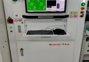
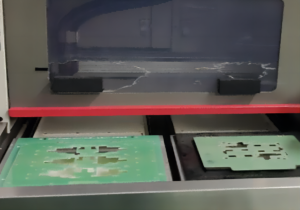
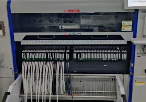
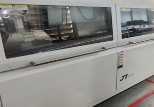
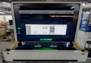
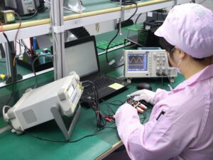
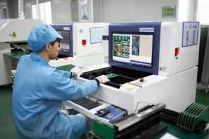
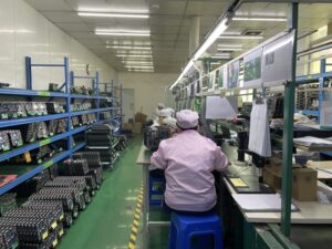
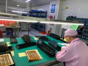
Contamos con una amplia capacidad de procesamiento de PCBs. Desde el diseño hasta la entrega, tenemos los equipos y procesos necesarios para asegurarnos de que tu pedido se realice correctamente. -
Entrega Rápida
Cumple tus plazos con nuestros tiempos de entrega rápidos.
Nuestra producción optimizada asegura tiempos de entrega rápidos, para que recibas tus productos cuando los necesites, sin retrasos.
Proyectos Relacionados que Hemos Realizado
Opiniones de Clientes
Preguntas Comunes
Preguntas Más Populares
Envíanos un mensaje
Cuanto más detallado completes, más rápido podremos avanzar al siguiente paso.




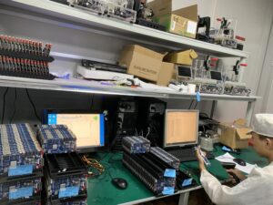






Guía Completa para el Diseño de PCBs Multicapa
Contenido
Capítulo 1

Introducción a los PCBs Multicapa
¿Qué son los PCBs Multicapa y por qué son importantes?
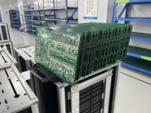
Un PCB Multicapa (Placa de Circuito Impreso) es un tipo complejo de placa de circuito que consiste en múltiples capas de componentes eléctricos intercaladas entre capas de material aislante. A diferencia de los PCBs de una sola capa, que tienen componentes solo en un lado de la placa, los PCBs multicapa apilan varias capas una sobre otra, separadas por material aislante. Este diseño permite integrar más componentes en un espacio más pequeño, aumentando la funcionalidad y eficiencia del dispositivo.
La transición de PCBs de una sola capa a multicapa
La transición de los PCBs de una sola capa a los multicapa representa un avance significativo en la tecnología de diseño electrónico. En los primeros días de la electrónica, los PCBs de una sola capa eran suficientes para los dispositivos electrónicos básicos. Sin embargo, a medida que la tecnología avanzó, creció la demanda de dispositivos más pequeños y de mayor velocidad, lo que llevó al desarrollo de PCBs de doble capa y, finalmente, multicapa.
Cada capa adicional permite una mayor densidad de componentes e interconexiones que no son posibles con diseños de una sola capa. Esta transición ha permitido la creación de dispositivos electrónicos cada vez más complejos y potentes.
Resumen de Componentes y Funcionalidad
Los principales componentes de un PCB multicapa incluyen:
Caminos Conductores (Trazos):
Líneas delgadas de cobre u otro material conductor que se graban en la placa y actúan como el cableado del circuito.
Capas Dieléctricas:
Estas capas aislantes separan las capas conductoras de cobre y previenen cortocircuitos eléctricos entre diferentes capas.
Vías:
Pequeños agujeros perforados en el PCB que permiten conexiones eléctricas entre diferentes capas. Las vías pueden ser de paso, ciegas o enterradas, dependiendo de si conectan todas las capas o solo algunas específicas.
Pads (Almohadillas):
Áreas expuestas de metal donde se sueldan los componentes.
En términos de funcionalidad, los PCBs multicapa ofrecen varias ventajas sobre los de una sola capa:
- Mayor Capacidad y Densidad: Soportan más circuitos por unidad de área, esencial para dispositivos modernos y compactos.
- Mejor Durabilidad: El diseño multicapa ofrece mayor protección contra factores ambientales como el calor y la humedad.
- Rendimiento Mejorado: La disposición de múltiples capas puede reducir las interferencias electromagnéticas (EMI) y las pérdidas de señal, cruciales para mantener la integridad de señales de alta velocidad.
Los PCBs multicapa han transformado la manera en que diseñamos dispositivos electrónicos, permitiendo avances tecnológicos mientras reducimos el tamaño de los equipos. Nos permiten integrar circuitos complejos en espacios pequeños, mejorando el funcionamiento y la durabilidad. Por eso los encontramos en casi todo hoy en día.
Capítulo 2
Por qué Deberías Usar PCBs Multicapa
Más Funcionalidad en Menos Espacio
Una de las mayores ventajas de los PCBs multicapa es que te permiten obtener más funcionalidad en un espacio más reducido. Esto es clave en industrias donde el espacio es un recurso limitado. Al apilar múltiples capas, estos PCBs crean espacio para más componentes e interconexiones. Esto significa que puedes integrar más funcionalidad en dispositivos más pequeños, como smartphones, smartwatches y implantes médicos, donde los PCBs tradicionales de una sola capa no serían suficientes.
Mayor Durabilidad y Fiabilidad
Al elegir un PCB multicapa, obtienes un producto más duradero. Las múltiples capas de materiales en estos PCBs incluyen aislantes de alta calidad que protegen las capas conductoras de cobre. Esta estructura no solo protege contra amenazas ambientales como la humedad y el estrés térmico, sino que también proporciona estabilidad mecánica. El resultado es un producto que resiste mejor el paso del tiempo, haciendo que los PCBs multicapa sean ideales para aplicaciones en entornos exigentes, como la electrónica automotriz, equipos militares y hardware de telecomunicaciones al aire libre.
Mejor Rendimiento con Menos Interferencia Electromagnética (EMI)
Con los PCBs multicapa, obtienes un mejor rendimiento, especialmente en términos de integridad de señal. Estos PCBs están diseñados con capas internas de alimentación y tierra que protegen las capas que transportan señales, lo que reduce significativamente la interferencia electromagnética (EMI). Esto los hace perfectos para circuitos de alta velocidad donde mantener la integridad de la señal es fundamental. Verás esta mejora en aplicaciones como centros de datos, routers de alta velocidad y sistemas avanzados de computación, donde incluso una pequeña interferencia puede causar errores de datos.
Cruciales para Dispositivos Compactos y de Alta Densidad Modernos
Las ventajas de los PCBs multicapa son especialmente críticas en la electrónica moderna, que no solo debe realizar múltiples funciones, sino también adaptarse a espacios cada vez más reducidos. Piensa en tu último smartphone o en un dron de última generación: estos dispositivos requieren configuraciones densas de componentes que solo los PCBs multicapa pueden soportar eficientemente. Además, la flexibilidad de diseño que ofrecen los PCBs multicapa permite una colocación óptima de los componentes, lo que mejora la conectividad y acorta las rutas de transmisión, aumentando el rendimiento general del dispositivo.
Usados en una Amplia Gama de Industrias
Los PCBs multicapa se utilizan en una amplia gama de industrias, incluyendo salud, electrónica de consumo, automoción y aeroespacial. En cada uno de estos campos, el tamaño reducido, la durabilidad y el rendimiento de los PCBs multicapa proporcionan la tecnología necesaria para impulsar la innovación. Ya sea tecnología vestible que monitorea tu salud, autos inteligentes ecológicos o electrónica aeroespacial, los PCBs multicapa están en el centro de los avances que empujan los límites de lo que la tecnología puede hacer.
Cuando usas PCBs multicapa en tus diseños, no solo estás siguiendo las tendencias actuales de la tecnología; estás preparando el terreno para futuras innovaciones. Con todos sus beneficios, estos PCBs no solo cumplen con los altos estándares de hoy, sino que también anticipan los desafíos del mañana, convirtiéndose en una pieza clave en la evolución de los dispositivos electrónicos.
Capítulo 3
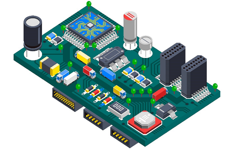
Consideraciones Clave para el Diseño de PCBs Multicapa
Diseñar un PCB multicapa es mucho más complicado que diseñar una placa de una sola capa. Aquí tienes algunos aspectos que debes considerar para garantizar que tu PCB multicapa funcione correctamente y sea confiable.
Elige el Material Adecuado
Elegir el material adecuado es crucial al diseñar un PCB multicapa. El material afecta desde la durabilidad de la placa hasta su capacidad de conducción eléctrica. El material más común es el FR-4, un laminado de fibra de vidrio y resina epoxi. Es popular porque ofrece un buen equilibrio entre costo y rendimiento. Si estás trabajando en una aplicación de alta frecuencia, podrías necesitar un material más avanzado como Rogers o Teflón, que tienen menores pérdidas dieléctricas.
El material elegido afecta la capacidad de tu PCB para manejar el calor, su resistencia mecánica y su conductividad eléctrica. Por ejemplo, los materiales con un bajo coeficiente de expansión térmica (CTE) manejan mejor el calor y son menos propensos a problemas mecánicos cuando la temperatura cambia. Esto es especialmente importante en dispositivos de alta densidad o alta potencia, donde el calor es un factor crítico.
Decide Cuántas Capas Necesitas
Decidir cuántas capas necesita tu PCB es un factor clave, ya que afecta el costo y las capacidades de la placa. Más capas permiten integrar más componentes y circuitos complejos, lo que es esencial para la electrónica de alto rendimiento. Sin embargo, cada capa adicional aumenta el costo y la complejidad de fabricación.
Al decidir el número de capas, considera la importancia de la integridad de las señales y las necesidades eléctricas de tu placa. Si trabajas con señales muy rápidas, puede que necesites capas específicas para alimentación y tierra, para garantizar un funcionamiento correcto y reducir las interferencias entre señales.
Ancho de las Rutas: Garantizar la Integridad de la Señal y la Gestión de Energía
El ancho de las líneas en tu PCB es fundamental porque determina cuánto corriente puede manejar la placa sin sobrecalentarse y cómo se comportan las señales. Las líneas más delgadas permiten integrar más componentes en un espacio reducido, pero pueden no soportar corrientes altas, lo que podría causar sobrecalentamiento o fallos.
El ancho de las líneas también es importante para garantizar una impedancia adecuada, especialmente en circuitos de alta velocidad. Una impedancia correcta evita reflejos y alteraciones en las señales. Existen herramientas de software que te ayudan a calcular el ancho de línea adecuado según la corriente y la impedancia que requiere tu proyecto.
Abordar la Interferencia Electromagnética (EMI) y la Diafonía
En el diseño de un PCB multicapa, es fundamental minimizar las interferencias entre señales y protegerlas del ruido externo. Una estrategia efectiva es incluir planos de alimentación y tierra correctamente ubicados, lo que ayuda a reducir las interferencias electromagnéticas (EMI). También es importante diseñar el enrutamiento de las señales cuidadosamente.
El uso de señalización diferencial puede proteger las señales del ruido. Además, debes garantizar suficiente espacio entre las rutas para evitar diafonías que podrían afectar la integridad de las señales.
Diseño de Vías: Conectar las Capas de Forma Efectiva
Las vías son un componente crítico en el diseño de un PCB multicapa. Debes decidir si usar vías de paso, ciegas o enterradas, según las necesidades del diseño y tu presupuesto. Las vías de paso son las más económicas y fáciles de fabricar, pero ocupan más espacio. Las vías ciegas y enterradas ahorran espacio y mejoran el rendimiento, aunque son más costosas y complicadas de fabricar.
Si consideras cuidadosamente todos estos aspectos—el material, el número de capas, el ancho de las rutas, la mitigación de interferencias y el diseño de las vías—podrás crear un PCB multicapa que funcione de manera eficiente y no sea excesivamente costoso. Estas decisiones no solo afectan el rendimiento de la placa, sino también su costo y la facilidad de fabricación. Para tu próximo diseño, ten en cuenta estos factores para garantizar una placa bien diseñada y fácil de producir.
Capítulo 4
Proceso Paso a Paso para Diseñar PCBs Multicapa
Diseñar un PCB multicapa es una actividad sistemática que debe ejecutarse cuidadosamente. No importa si eres un diseñador profesional de PCBs o estás comenzando, seguir un enfoque estructurado garantizará la funcionalidad y confiabilidad de tu producto final. Sigue estos pasos y tendrás éxito en diseñar tu primer PCB multicapa.
Paso 1: Idea y Análisis de Requisitos
Antes de comenzar a diseñar tu PCB, debes tener claro qué quieres lograr y qué necesita hacer tu PCB. ¿Cuál es el propósito del PCB? ¿En qué condiciones ambientales se utilizará? Saber las respuestas a estas preguntas te ayudará a decidir qué materiales usar, qué componentes elegir y cuántas capas y conexiones necesitarás. Haz una lista de todos los componentes que planeas usar y recopila sus hojas de datos como referencia.
Paso 2: Diseño del Esquema
Utilizando una herramienta de diseño de PCBs, comienza creando el esquema de tu circuito. Esto implica dibujar un diagrama que muestre todos los componentes y cómo están conectados. Es muy importante verificar dos veces cada conexión en esta etapa, ya que los errores aquí pueden causar grandes problemas más adelante. Herramientas como OrCAD, Altium Designer o Eagle pueden utilizarse para el diseño del esquema. Estas herramientas proporcionan una representación visual que te ayuda a asegurarte de que todo esté en el lugar correcto y tenga sentido.
Paso 3: Planificación del Apilado de Capas
Después de completar tu esquema, necesitas planificar el apilado de capas. Esto significa decidir cuántas capas tendrá tu PCB y qué función tendrá cada una. Las configuraciones comunes incluyen capas de señales, planos de alimentación y planos de tierra. El objetivo es minimizar problemas de integridad de señal y gestionar las interferencias electromagnéticas (EMI). Para circuitos de alta velocidad, considera colocar planos de tierra junto a las capas de señales para proporcionar apantallamiento y control de impedancia.
Paso 4: Diseño del Layout
Pasa del esquema al diseño del layout en tu software de PCB. Aquí, colocarás los componentes y enrutarás las trazas entre ellos según las conexiones definidas en el esquema. Presta mucha atención a la ubicación de los componentes críticos para minimizar la longitud de las trazas, reduciendo retrasos e interferencias. Usa herramientas de enrutamiento automático con ajustes manuales para optimizar las rutas y asegúrate de que las trazas sean lo suficientemente anchas para manejar la corriente y cumplir con los requisitos de impedancia.
Paso 5: Verificación y Comprobaciones de Integridad de Señal
Una vez que hayas terminado el layout, debes asegurarte de que todo cumpla con los requisitos. Usa las herramientas en tu software de diseño de PCB para verificar errores como trazas cruzadas, espacio insuficiente entre trazas y componentes, y otros problemas potenciales. Realiza un análisis de integridad de señal para garantizar que todas las señales se transmitan con mínimas pérdidas e interferencias. Este paso puede requerir varias iteraciones para perfeccionar el diseño y optimizar el rendimiento.
Paso 6: Fabricación del Prototipo
Una vez que hayas verificado tu diseño, estarás listo para fabricar un prototipo. Esto te permitirá probar tu PCB en condiciones reales y detectar posibles problemas de funcionalidad o rendimiento. Elige un fabricante de PCBs confiable y envíales tus archivos de diseño, generalmente en formato Gerber, que contiene todos los datos necesarios para fabricar tu PCB.
Paso 7: Pruebas e Iteraciones
Prueba tu prototipo en condiciones similares a las de su uso final. Verifica su funcionalidad y cualquier diferencia en el rendimiento. Si encuentras problemas, regresa a tu diseño y realiza los cambios necesarios. Esto podría implicar volver a cualquiera de los pasos anteriores, desde modificar el esquema hasta ajustar el layout o cambiar el apilado.
Paso 8: Producción Final
Después de probar tu prototipo y realizar los cambios necesarios, tu diseño de PCB estará listo para la producción. Esto implica escalar el proceso de fabricación para producir tantas PCBs como necesites, asegurándote de que cada lote se fabrique con los mismos estándares de calidad que el prototipo.
Si sigues estos pasos cuidadosamente, podrás diseñar y fabricar un PCB multicapa de alta calidad que cumpla con tus requisitos y funcione de manera confiable en el mundo real. Cada paso es importante y requiere reflexión cuidadosa para garantizar el éxito de tu producto electrónico.
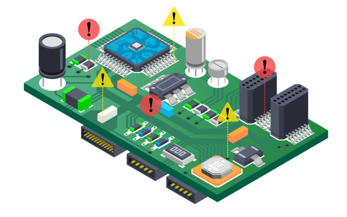
Capítulo 5
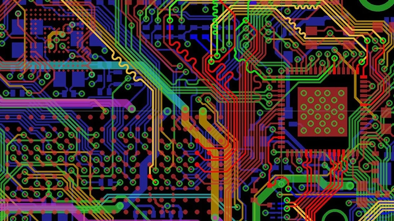
Estrategias para Crear un Apilado de Capas Efectivo en PCBs Multicapa
Cuando diseñas el apilado de capas para tu PCB multicapa, es como construir los cimientos de un edificio: es fundamental para la estabilidad, funcionalidad e integridad de tu placa. En este capítulo, exploraremos estrategias para crear un apilado de capas efectivo, enfocándonos en mejorar tanto la integridad de señales como la de la energía.
Comprendiendo el Apilado de Capas
El apilado de capas define cómo se organizan las diferentes capas (señal, alimentación y tierra) en un PCB multicapa. Esta disposición afecta el rendimiento eléctrico de la placa, así como su fabricabilidad y costo. Un apilado óptimo ayuda a minimizar problemas de integridad de señales, gestionar las interferencias electromagnéticas (EMI) y garantizar una distribución de energía robusta.
Estrategia 1: Enfócate en la Integridad de Señales
Para mantener la integridad de señales, tu apilado debe minimizar la distancia que las señales recorren entre componentes, reduciendo la pérdida de señal y la diafonía. Aquí hay algunas recomendaciones:
- Empareja Capas Adyacentes: Coloca las capas de señal junto a planos de tierra o alimentación. Esto protege las capas de señal y proporciona un camino de retorno para las señales, reduciendo la diafonía y las EMI.
- Simetría y Balance: Intenta mantener el apilado simétrico para evitar que la placa se deforme durante la fabricación. Un apilado simétrico también asegura características eléctricas consistentes en la placa.
Estrategia 2: Perfecciona la Integridad de la Energía
La integridad de la energía se refiere a mantener una distribución de energía estable y limpia en toda la placa. Para lograrlo, debes colocar estratégicamente las capas de alimentación y tierra:
- Planos Dedicados para Alimentación y Tierra: Usa capas exclusivas para la alimentación y la tierra. Esto reduce la impedancia de la red de distribución de energía y permite manejar de manera efectiva la carga de corriente, algo crítico en aplicaciones de alta potencia.
- Mantén las Capas de Alimentación y Tierra Cercanas: Al colocar planos de alimentación y tierra cerca uno del otro, reduces la inductancia general.
Estrategia 3: Minimiza las EMI y los Problemas Térmicos
Un apilado de capas efectivo también puede ayudar a minimizar las EMI y gestionar el rendimiento térmico:
- Intercala Planos de Tierra: Usa múltiples capas de tierra intercaladas entre capas de señal. Este diseño actúa como un escudo contra EMI y ayuda a disipar el calor, especialmente importante en aplicaciones de alta velocidad o alta frecuencia.
- Vías Térmicas: Incorpora vías térmicas en el apilado para transferir el calor de los componentes calientes a un disipador o al entorno externo, evitando el sobrecalentamiento.
Estrategia 4: Considera Tecnologías HDI (Interconexión de Alta Densidad)
Para diseños realmente complejos o compactos, considera usar tecnologías HDI. Las placas HDI tienen espacios y líneas más finas, vías más pequeñas y una mayor densidad de almohadillas de conexión que los PCBs tradicionales:
- Microvías: Usa microvías para conectar solo las capas necesarias, ahorrando espacio y mejorando la integridad de las señales de alta velocidad.
- Vías Apiladas: Emplea vías apiladas en áreas con alta densidad de componentes para maximizar el espacio y mejorar la conectividad entre capas.
Finaliza tu Apilado
Una vez que hayas planeado tu apilado de capas usando estas estrategias, revísalo con tu fabricante de PCBs. Ellos pueden ofrecerte información valiosa, especialmente en términos de fabricabilidad e implicaciones de costos. También pueden darte ideas sobre materiales y tecnologías más recientes que podrían optimizar aún más tu diseño.
Recuerda, el apilado de capas que elijas impacta directamente en el rendimiento y la confiabilidad de tu PCB multicapa. Al planificar cuidadosamente tu estrategia de apilado, garantizas que tu placa cumpla con todos los estándares eléctricos necesarios y funcione de manera confiable en su aplicación prevista.
Capítulo 6
Integridad de la señal y control de impedancia en PCBs multicapa
La integridad de la señal y el control de impedancia son dos de los aspectos más importantes en el diseño de PCBs multicapa, especialmente cuando se trabaja con circuitos electrónicos de alta velocidad. En este artículo, explicaremos por qué estos dos elementos son tan críticos y cómo puede gestionarlos de manera efectiva para garantizar que su PCB funcione de la mejor manera.
¿Qué es la integridad de la señal?
La integridad de la señal se refiere a la condición en la que las señales digitales y analógicas se transmiten sin una degradación significativa. En las PCBs multicapa, mantener la integridad de la señal es crucial porque cualquier distorsión o pérdida puede provocar errores de datos, inestabilidad del sistema y un rendimiento reducido. A medida que sus PCBs manejan señales más rápidas y frecuencias más altas, los desafíos relacionados con la integridad de la señal aumentan, haciendo que el diseño y el control meticuloso sean fundamentales.
El papel del control de impedancia
La impedancia es la medida de oposición que un circuito presenta a una corriente cuando se aplica un voltaje. En el diseño de PCBs, controlar la impedancia implica garantizar que la impedancia de las trazas de la PCB coincida con las impedancias de la fuente y la carga. Esta coincidencia es crucial para prevenir reflexiones y pérdidas de señal, que pueden ocurrir si hay desajustes de impedancia a lo largo del camino de la señal.
A continuación, le mostramos cómo garantizar un control de impedancia efectivo y mantener la integridad de la señal:
Estrategia 1: Use trazas de impedancia controlada
- Ancho y espaciado de las trazas: Determine el ancho y el espaciado de las trazas según el material dieléctrico y el grosor de la PCB. Utilice software de diseño de PCBs para calcular las dimensiones óptimas que lograrán la impedancia deseada.
- Geometría de traza consistente: Mantenga una geometría de traza consistente en todo el circuito para evitar discontinuidades de impedancia.
Estrategia 2: Optimice la configuración de capas de la PCB
- Configuración simétrica: Diseñe una configuración simétrica cuando sea posible.
- Planos de tierra y alimentación adyacentes: Coloque planos de tierra y alimentación adyacentes a las capas de señal para proporcionar blindaje y reducir el área del bucle.
Estrategia 3: Minimice la diafonía
- Enrutamiento de trazas adecuado: Rute trazas paralelas lo más separadas posible.
- Evite las curvas de 90 grados: Use transiciones más suaves como ángulos de 45 grados.
Estrategia 4: Gestione las vías de señal
- Longitudes de traza más cortas: Mantenga las trazas lo más cortas posible.
- Diseño de vías: Use vías con cuidado para evitar discontinuidades.
Pruebas y verificación
- Pruebas TDR: Use pruebas TDR para medir el perfil de impedancia.
- Herramientas de simulación: Utilice software de simulación para analizar la integridad de la señal.
Capítulo 7

Gestión térmica en PCBs multicapa
La gestión térmica efectiva es un aspecto crucial del diseño de PCBs multicapa, especialmente a medida que los dispositivos se vuelven más compactos y aumentan las densidades de potencia. Aquí tiene una guía sobre cómo enfrentar los desafíos de la gestión del calor en sus diseños de PCBs y garantizar que sus dispositivos funcionen de manera confiable sin sobrecalentarse.
Los desafíos de la gestión térmica en PCBs multicapa
A medida que las PCBs multicapa integran más componentes en áreas más pequeñas, el calor generado puede concentrarse, llevando a temperaturas más altas. Este aumento de temperatura puede afectar el rendimiento, la confiabilidad y la vida útil de los componentes electrónicos. La gestión efectiva de este calor es crucial, particularmente en aplicaciones de alta potencia como sistemas de iluminación LED, convertidores de potencia y procesadores de computadoras, donde el exceso de calor puede causar fallas.
Técnicas para una disipación de calor efectiva
Aquí hay varias estrategias y técnicas que puede utilizar para mejorar la gestión térmica en sus PCBs multicapa:
1. Vías térmicas
- Colocación de vías: Coloque vías térmicas directamente debajo o muy cerca de los componentes que generan calor.
- Diseño de vías: Use vías de mayor diámetro y mayor densidad para mejorar la conductividad térmica.
2. Selección de materiales
- Conductividad térmica: Seleccione materiales con alta conductividad térmica para el sustrato.
- PCBs con núcleo metálico: Considere usar PCBs con núcleo metálico (MCPCBs) para aplicaciones de potencia extremadamente alta.
3. Configuración de la pila de capas
- Capas de disipación de calor: Integre capas dedicadas como disipadores térmicos.
- Planos de tierra y alimentación: Utilice planos de cobre para tierra y alimentación.
4. Colocación y diseño de componentes
- Evite la concentración de calor: Distribuya los componentes que consumen mucha energía.
- Alivio térmico: Coloque componentes sensibles al calor en áreas con buena ventilación.
5. Disipadores de calor y soluciones de enfriamiento
- Disipadores de calor: Coloque disipadores directamente en los componentes que generan calor.
- Enfriamiento activo: Utilice ventiladores o sistemas de enfriamiento líquido.
Pruebas y verificación
Finalmente, es importante probar su PCB bajo condiciones operativas realistas para verificar la efectividad de sus estrategias de gestión térmica. Cámaras térmicas y sensores pueden ayudar a detectar puntos calientes.
Capítulo 8
Errores comunes y cómo evitarlos
El diseño de PCBs multicapa puede ser una tarea compleja, llena de posibles errores que podrían comprometer el rendimiento y la confiabilidad de sus dispositivos electrónicos. Ser consciente de estos problemas comunes y saber cómo evitarlos le ayudará a garantizar un proceso de diseño más fluido y un producto final más robusto. Aquí tiene una guía sobre los desafíos típicos que podría enfrentar y las mejores prácticas para superarlos.
Error 1: Planificación inadecuada de la integridad de la señal
Problema: No planificar adecuadamente la integridad de la señal puede ocasionar problemas como pérdida de señal, diafonía e interferencia electromagnética (EMI), especialmente críticos en circuitos de alta velocidad.
Solución: Planifique siempre la configuración de capas pensando en la integridad de la señal. Use planos de tierra adyacentes a las capas de señal para proporcionar blindaje y mantener el control de impedancia. Considere utilizar pares diferenciales para señales críticas y asegúrese de minimizar y ajustar las longitudes de las trazas en rutas de señal clave.
Error 2: Mala gestión térmica
Problema: Las PCBs multicapa a menudo sufren de una gestión térmica inadecuada, lo que lleva al sobrecalentamiento y a una vida útil reducida de los componentes.
Solución: Use vías térmicas estratégicamente ubicadas debajo o alrededor de los componentes que generan calor para facilitar la transferencia de calor a un disipador o a las capas exteriores. Seleccione materiales con mayor conductividad térmica para las capas cercanas a las fuentes de calor y considere incorporar una capa con núcleo metálico si se espera un calor extremo. Además, asegúrese de un espaciamiento adecuado entre componentes de alta potencia para evitar puntos calientes.
Error 3: Uso incorrecto de vías
Problema: Las vías mal ubicadas o diseñadas pueden causar problemas como conexiones rotas y discontinuidades de impedancia.
Solución: Planifique cuidadosamente la ubicación de las vías para minimizar la distancia que deben recorrer las señales eléctricas, reduciendo la latencia y la degradación de la señal. Use vías ciegas o enterradas para ahorrar espacio y reducir las conexiones entre capas cuando no sea necesario interconectar todas las capas. Asegúrese de que las vías tengan el tamaño adecuado para soportar la carga de corriente y no comprometan la integridad estructural de la placa.
Error 4: Diafonía entre trazas
Problema: La diafonía es un problema frecuente en PCBs multicapa densamente empaquetadas, donde el campo electromagnético de una traza afecta a otra, causando interferencias no deseadas.
Solución: Aumente la distancia entre trazas paralelas o coloque un plano de tierra entre ellas para reducir el acoplamiento capacitivo e inductivo. Rute trazas críticas de manera perpendicular si deben cruzarse y considere usar trazas blindadas para señales altamente sensibles.
Error 5: Colocación incorrecta de componentes
Problema: La colocación inadecuada de los componentes puede causar dificultades en el enrutamiento, interferencias electromagnéticas y desequilibrios térmicos.
Solución: Agrupe componentes similares para minimizar la longitud de las conexiones críticas y utilice herramientas de simulación para verificar problemas de compatibilidad electromagnética (EMC). Mantenga los componentes sensibles alejados de los componentes de alta frecuencia o alta potencia y asegúrese de dejar suficiente espacio para la disipación de calor.
Error 6: Pasar por alto las limitaciones de fabricación
Problema: Diseñar sin considerar las capacidades de fabricación puede resultar en una PCB demasiado costosa o imposible de producir.
Solución: Involucre a su fabricante de PCBs desde el principio del proceso de diseño para comprender sus capacidades y limitaciones. Diseñe de acuerdo con sus especificaciones para anchos de traza, espaciado y dimensiones de vías para garantizar la manufacturabilidad y mantener los costos bajo control.
Error 7: Pruebas y verificaciones insuficientes
Problema: Saltarse fases de prueba exhaustivas puede provocar problemas no detectados en el producto final.
Solución: Implemente un protocolo de pruebas riguroso que incluya simulaciones de software para el rendimiento eléctrico y pruebas físicas para la confiabilidad térmica y mecánica. Use herramientas como Reflectometría en el Dominio del Tiempo (TDR) para analizar la impedancia e imágenes térmicas para detectar puntos calientes y evaluar el rendimiento térmico.
Capítulo 9

Pruebas y solución de problemas en PCBs multicapa
Garantizar la funcionalidad y confiabilidad de sus PCBs multicapa requiere pruebas exhaustivas y una solución de problemas eficiente. Aquí le mostramos cómo probar metódicamente sus PCBs y solucionar eficazmente los problemas comunes para asegurarse de que su producto cumpla con los estándares de rendimiento y durabilidad.
Pruebas de PCBs multicapa
1. Pruebas eléctricas:
- Prueba de continuidad: Este debe ser su primer paso. Verifica que todas las conexiones en la PCB estén correctamente realizadas y que no haya cortocircuitos. Utilice un multímetro o un equipo de prueba automatizado (ATE) para comprobar cada punto de conexión según los archivos de diseño de la PCB.
- Prueba en circuito (ICT): La ICT es más completa, ya que verifica cortocircuitos, circuitos abiertos, resistencia, capacitancia y otros parámetros eléctricos que pueden afectar la funcionalidad de la PCB. Requiere acceso físico a todos los nodos, así que planifique puntos de prueba en su diseño.
2. Pruebas funcionales:
- Prueba de encendido: Aplique energía a la PCB y monitoree las respuestas iniciales. Verifique los voltajes esperados en varios puntos y observe comportamientos inesperados como reinicios o fallos de inicio.
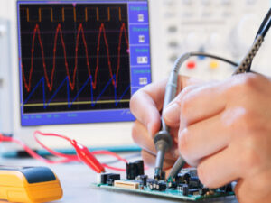
- Prueba de integridad de la señal: Utilice osciloscopios y analizadores lógicos para asegurarse de que las señales de alta velocidad sean limpias y estén libres de ruido y distorsión indebidos. Esta prueba es crucial para circuitos que involucren componentes de alta frecuencia.
3. Pruebas ambientales:
- Ciclo térmico: Exponga la PCB a diversas temperaturas para asegurarse de que pueda manejar el estrés ambiental. Esto ayuda a identificar fallos potenciales causados por la expansión térmica.
- Prueba de humedad: Simule entornos de alta humedad para comprobar posibles fallos debido a la condensación o la entrada de humedad, que pueden causar corrosión o cortocircuitos.
Capítulo 10
Tendencias futuras en el diseño de PCBs multicapa
A medida que la tecnología continúa avanzando, también lo hacen las técnicas y materiales utilizados en el diseño de PCBs. Aquí tiene un vistazo al futuro del diseño de PCBs multicapa, destacando las innovaciones que podrían revolucionar cómo se abordan estos sistemas complejos.
1. PCBs flexibles y extensibles
Imagine PCBs que puedan doblarse, flexionarse e incluso estirarse. Los PCBs flexibles y extensibles están destinados a ampliar las posibilidades del diseño electrónico, particularmente en tecnología portátil, dispositivos médicos e incluso aplicaciones automotrices. Estos PCBs utilizan materiales como la película de poliimida o poliéster, que les permite adaptarse a superficies no tradicionales o moverse sin romperse. Esta adaptabilidad abre nuevas oportunidades de diseño para dispositivos que deben operar en entornos dinámicos o irregulares.
2. Herramientas de diseño impulsadas por IA
La inteligencia artificial y el aprendizaje automático están transformando la forma en que se diseñan los PCBs. Las herramientas de diseño basadas en IA pueden automatizar procesos complejos como el ruteo y la optimización del diseño, reduciendo significativamente el tiempo de diseño y los posibles errores. Estas herramientas analizan grandes cantidades de datos para sugerir diseños óptimos según criterios predefinidos, como minimizar el ruido o reducir los costos de materiales. A medida que la tecnología de IA progresa, estas herramientas ofrecerán ideas aún más sofisticadas, agilizando aún más el proceso de diseño.
3. Integración de materiales avanzados
El uso de materiales avanzados en PCBs multicapa está en aumento. Materiales como el grafeno y los polímeros conductores están siendo explorados por sus propiedades eléctricas, térmicas y mecánicas excepcionales. Por ejemplo, el grafeno ofrece una excelente conductividad eléctrica y capacidades de gestión térmica, lo que podría llevar a placas más rápidas y con menor temperatura. A medida que estos materiales sean más accesibles, podrían mejorar dramáticamente el rendimiento y la durabilidad de los PCBs.
4. Impresión 3D de PCBs
La tecnología de impresión 3D está preparada para transformar la fabricación de PCBs, permitiendo prototipos rápidos y diseños multicapa complejos que son difíciles de lograr con métodos de fabricación tradicionales. La impresión 3D permite la integración directa de componentes electrónicos en la PCB durante el proceso de fabricación, reduciendo el tiempo de ensamblaje y potencialmente mejorando la confiabilidad de las placas terminadas.
5. Avances en la tecnología HDI
La tecnología de interconexión de alta densidad (HDI), que permite líneas y espacios más finos, vías más pequeñas y una mayor densidad de componentes, se espera que evolucione aún más. Los futuros desarrollos pueden incluir microvías aún más pequeñas y materiales mejorados para el llenado de vías, mejorando el rendimiento eléctrico y la confiabilidad de las placas. Esto será crucial para apoyar la tendencia continua hacia la miniaturización en la electrónica.
6. Soluciones mejoradas de gestión térmica
A medida que los componentes se vuelven más pequeños y aumentan las densidades de potencia, la gestión del calor en PCBs multicapa es aún más crítica. Las tendencias futuras incluyen la integración de técnicas de enfriamiento novedosas, como canales de enfriamiento integrados o capas térmicamente conductoras que puedan extraer activamente el calor de los puntos calientes. Estas innovaciones serán esenciales para la computación de alto rendimiento y la electrónica de potencia.
7. Herramientas más robustas de simulación y prueba
Se esperan avances en el software de simulación que pueda modelar con mayor precisión los comportamientos eléctricos, térmicos y mecánicos. Estas herramientas ayudarán a los diseñadores a predecir cómo funcionarán los PCBs multicapa en diversas condiciones antes de que se fabriquen físicamente, reduciendo la necesidad de múltiples prototipos y asegurando que el producto final cumpla con todas las especificaciones.

Póngase en Contacto
¿Dónde Estamos?
Parque Industrial, No. 438 Donghuan Road, No. 438, Shajing Donghuan Road, Distrito de Bao'an, Shenzhen, Guangdong, China
Cuarto Piso, Edificio Creativo Zhihui, No.2005 Xihuan Road, Shajing, Distrito de Baoan, Shenzhen, China
Habitación A1-13, Tercer Piso, Centro Industrial Yee Lim, 2-28 Calle Kwai Lok, Kwai Chung, HK
service@southelectronicpcb.com
Teléfono: +86 400 878 3488
Envíanos un mensaje
Cuanto más detallado completes, más rápido podremos avanzar al siguiente paso.


