
Your smartphone just crashed during a summer road trip. The culprit? Overheating circuits. Welcome to the thermal limits of standard PCBs – and why High Tg PCBs are becoming electronics’ new heat armor.
High Tg PCBs use materials with glass transition temperatures above 170°C, preventing warping and failure in extreme heat. They enable reliable operation in demanding environments like engine control units and 5G base stations where standard boards collapse.
But raw temperature numbers only tell half the story. Let’s break down why these specialized boards are reshaping electronics design – and when you absolutely need them.
Why Are High Tg PCBs Necessary for Modern Electronics?
Imagine your autonomous car’s brain melting in Phoenix desert heat. With conventional FR4 PCBs, that’s not sci-fi – it’s a real reliability time bomb.
High Tg PCBs[^1] prevent thermal breakdown[^2] in power-dense electronics through three key advantages:
- Stable dielectric properties[^3] at 150°C+
- Lower Z-axis expansion (CTE < 3.5%)
- Reduced delamination risks during lead-free reflow
)
Thermal Performance Breakdown
| Parameter | Standard FR4 | High Tg Material | Improvement |
|---|---|---|---|
| Tg Temperature | 130-140°C | 170-180°C | +30% |
| T288 Survival Time | 20 minutes | 10x longer | |
| CTE Z-axis | 4.5% | 2.8% | 38% reduction |
| Thermal Conductivity | 0.3 W/mK | 0.6 W/mK | Double |
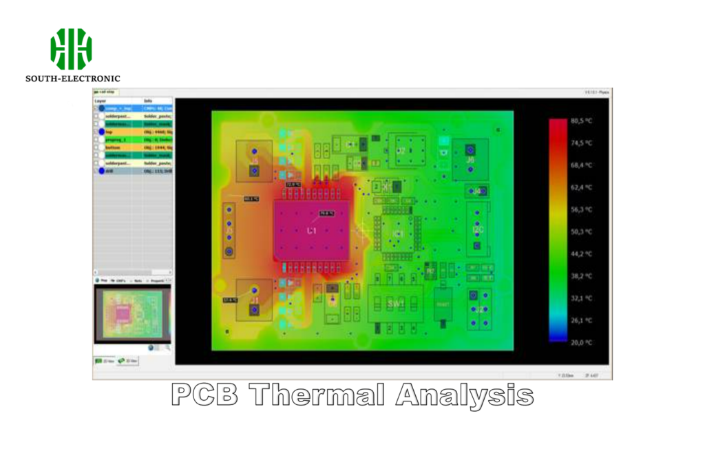
Modern smartphone processors now generate 5-10W/cm² – matching nuclear reactor fuel rod densities. High Tg substrates prevent the "slow bake" effect where repeated heating cycles degrade signal integrity. Automotive ECUs specifically require Tg 150°C+ boards to survive under-hood temperatures exceeding 125°C.
How Is High Tg PCB Material Different from Standard FR4?
Think of FR4 as household butter and High Tg materials as industrial-grade polymer binders. Both serve structural roles, but fail catastrophically if swapped.
High Tg laminates replace standard epoxy with:
- Phenolic cured resins
- Reinforced ceramic fillers
- Multi-stage crosslinking
Resulting in 25% higher mechanical strength and 50% better thermal resistance versus FR4.
)
Material Composition Analysis
FR4 Baseline
- Brominated epoxy resin
- Woven glass reinforcement
- Dicyandiamide curing
| High Tg Upgrade | Component | Purpose | Performance Impact |
|---|---|---|---|
| Tetrafunctional epoxy | Increased crosslinks | Higher Tg, lower CTE | |
| Alumina fillers | Thermal path enhancement | 0.6 W/mK conductivity | |
| Phosphorus flame retardant | UL94 V-0 compliance | Safer high-current operation |
The resin chemistry shift allows High Tg boards to withstand 10+ thermal cycles between -55°C and 260°C without cracking. This proves critical for aerospace applications experiencing rapid atmospheric changes.
What Applications Require High Tg PCBs?
Your factory’s laser cutter just shut down mid-operation. The root cause? Vibration-induced PCB fractures in standard control boards.
High Tg PCBs are mandatory in:
- Automotive ECUs (Tg ≥ 150°C)
- Downhole drilling electronics (175°C+ environments)
- Server power supplies (90°C continuous operation)
- High-altitude avionics (rapid thermal cycling)
)
Application Thermal Profiles
| Industry | Temperature Challenge | High Tg Solution |
|---|---|---|
| Electric Vehicles | Battery pack heat soak (140°C) | Tg 170°C substrates |
| Industrial IoT | Steam turbine monitoring | Low CTE for vibration zones |
| 5G Infrastructure | Power amplifier thermal density | Enhanced thermal dissipation |
| Aerospace | -65°C to 150°C cyclic stress | 50+ thermal cycles rating |
Automotive LED arrays showcase this perfectly – standard PCBs crack under headlamp thermal shock, while IS410-High Tg boards maintain optical alignment through 1,000+ temperature cycles.
What Design Considerations Are Critical for High Tg PCBs?
Designing with High Tg materials[^4] isn’t just a drop-in upgrade – it’s learning a new material language with different rules.
Key High Tg design factors:
- Tighter impedance control (ΔZ ±5% vs ±10%)
- Expanded drill-to-copper clearance (0.2mm min)
- Modified lamination cycles (high-pressure stages)
- Specialized surface finishes (ENIG preferred)
)
Manufacturing Adjustments Checklist
| Process Step | Standard FR4 | High Tg Adaptation |
|---|---|---|
| Drilling | 45K RPM | 40K RPM (reduced tool wear) |
| Lamination | 180°C @ 300psi | 200°C @ 500psi multi-stage |
| Desmear | Permanganate treatment | Plasma cleaning required |
| Soldermask | LPI 150°C cure | High-stability LPI 170°C+ |
A recent automotive project[^5] highlighted these needs – switching to IT-180G High Tg material required 15% longer lamination times but reduced field failures by 80% in engine control modules.
Conclusion
High Tg PCBs solve thermal reliability challenges[^6] in demanding electronics through advanced materials science, enabling next-gen applications from autonomous vehicles to edge AI processors.
[^1]: Explore how High Tg PCBs enhance reliability and performance in extreme heat, crucial for modern electronics.
[^2]: Understanding thermal breakdown can help you appreciate the importance of advanced materials in electronics design.
[^3]: Learn about dielectric properties to grasp their role in preventing failures in high-temperature environments.
[^4]: Explore how High Tg materials enhance thermal reliability and performance in demanding applications.
[^5]: Discover innovative solutions and case studies that highlight the importance of advanced PCB materials in automotive applications.
[^6]: Understanding these challenges can help in selecting the right materials and designs for optimal performance.

