
I see constant confusion about board-to-wire connectors in prototypes. You fix one electrical glitch, another pops up elsewhere! But understanding these tiny bridges unlocks reliable electronics. Let me clarify exactly how they link boards to wires.
Board-to-wire connectors create electrical paths between PCBs and cables using two mated parts: one soldered to the board and another holding wires secured by crimping. They bridge power/signals by physically joining metal contacts when plugged together.
These connectors are fundamental yet misunderstood. Stick around as I dissect practical application challenges and emerging innovations reshaping this critical component.
How to Prevent Common Failures in PCB Wire Connectors?
Faulty connectors crash entire systems overnight. I’ve seen projects derailed by simple contact failures! Prevent headaches by addressing frequent failure points proactively.
Key prevention strategies: verify proper pin seating, use strain relief for cables, maintain contact cleanliness, and ensure secure crimps without wire damage. Avoid vibration damage by adding locking clips.
Why Do They Fail?
Three core factors cause failures:
| Failure Type | Cause | Prevention |
|---|---|---|
| Broken contacts | Vibration/fatigue | Shock-absorbing mounts |
| Corrosion | Moisture/contaminants | IP-rated sealing |
| Poor connection | Misinsertion/cold solder | X-ray inspection guides |
Vibration stresses connections most. In my first robotics project, loose connectors caused weeks of troubleshooting. Now I always add silicone strain relief sleeves. Thermal cycling accelerates cracks too – automotive connectors integrate expansion gaps. Corrosion sneaks in through fingerprint acids or humidity; gold plating blocks this but costs more. Prevention balances reliability needs with budgets.
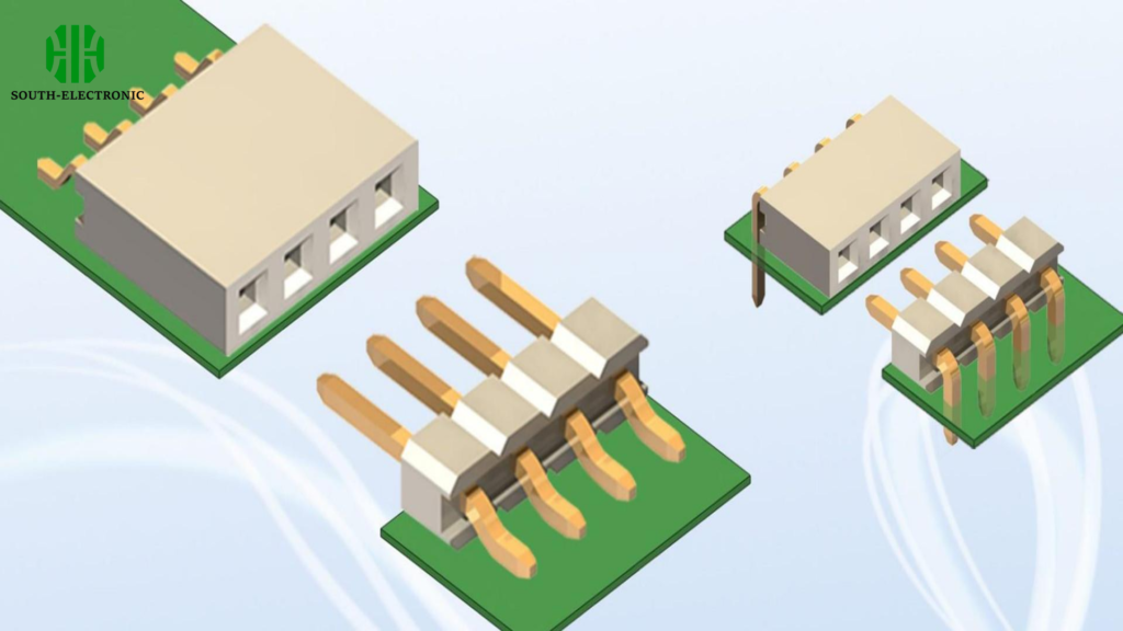
SMT vs Through-Hole: Which Termination Is Better for Your Wire Connectors?
Your PCB assembly method impacts durability critically. I chose wrong once, costing months in redesigns! Understanding trade-offs prevents such disasters.
Through-hole suits high-stress applications needing strength, while SMT fits automated production for space-constrained boards. Choose based on your physical demands and manufacturing setup.

Breaking Down the Differences:
| Criteria | Through-Hole | SMT |
|---|---|---|
| Shear strength | High | Moderate |
| Assembly cost | Higher labor | Lower automation |
| Fault repairability | Easy | Difficult |
| Board real estate | More space | Compact |
Through-hole pins penetrate boards, anchoring against pulls and twists. I use them in industrial controllers needing vibration resistance. SMT connectors mount faster via reflow ovens but risk detachment from side impacts – fine for stationary devices like routers. Mix techniques strategically: through-hole for power lines, SMT for signal pins. New hybrid connectors offer pin-through-paste options bridging both benefits.
What Innovations Are Transforming Board-to-Wire Connection Technology?
Stagnant connectors lag behind modern electronics. As devices shrink, traditional solutions choke innovation. Recent advancements solve this bottleneck beautifully.
RF connectors with impedance matching, modular blind-mate systems, and self-sealing IP68 units are revolutionizing connections. Integration of spring probes and push-in wire terminals also accelerates assembly.
Next-Generation Evolution:
Three disruptive trends:
| Innovation | Function | Application |
|---|---|---|
| Hybrid clips | Tool-free push-in wire terminals | Field repairs |
| Mezzanine arrays | Stackable micro-connectors | Wearable devices |
| Smart diagnostics | Embedded connection sensors | Predictive maintenance |
My drone project demanded ultralight connections – I used spring-loaded Pogo pin arrays saving 60% weight versus classics. In humid areas, self-sealing connectors with silicone gaskets prevent corrosion without added seals. For production, tool-free terminals reduce assembly errors significantly. Upcoming AI-enabled connectors could detect micro-failures before they cascade. This convergence of materials science and digital tech defines the future.
Conclusion
Board-to-wire connections bridge PCBs and cables through mechanical mating. Choosing termination methods wisely and adopting innovations prevents failures while enabling advanced electronics.

