

Overheating components can kill your PCB project fast. I’ve seen costly failures when heat spirals out of control. Don’t let poor thermal design ruin your hardware dreams—this guide will rescue you.
Choose heatsinks by evaluating material, geometry, placement, thermal interface material (TIM), and manufacturing process. For instance, aluminum saves cost while copper boosts conduction. Match this to your budget, device size, and heat output for optimal cooling and reliability.
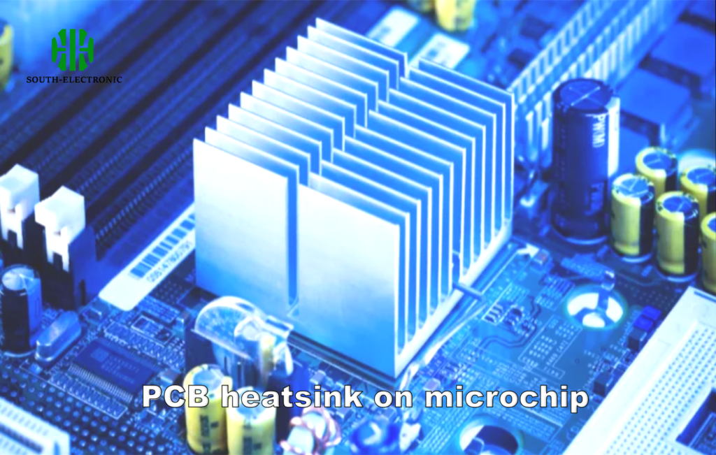
Picking components is just step one—install and design choices make or break performance. We’ll uncover key pitfalls to avoid catastrophic failures.
What’s the Best Way to Fix Heatsinks onto a Board?
A loose heatsink risks short circuits. Last month, thermal paste failure melted a client’s prototype. Securing them properly prevents disasters.
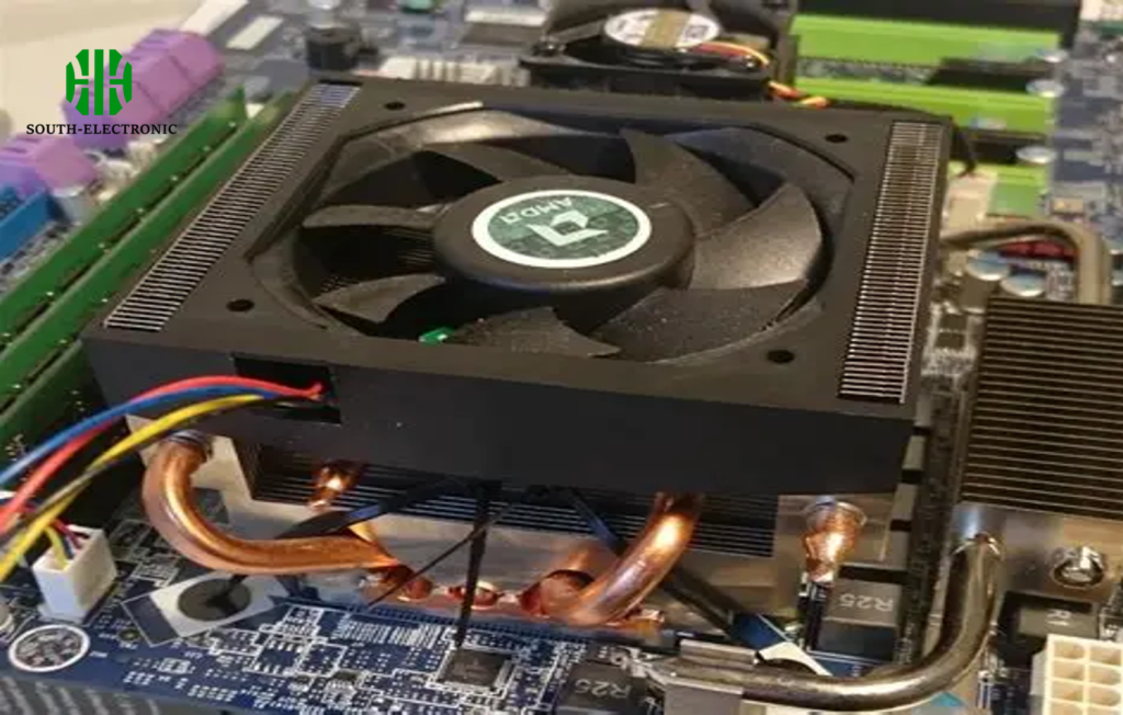
Use screws for heavy heatsinks, clips for low-weight designs, or thermal adhesive/epoxy when space is tight. Always pair them with quality thermal paste or pads to fill microscopic gaps and maximize heat transfer.
Comparing Fixation Options
Attachment matters more than you think. Wrong methods increase thermal resistance or lead to mechanical stress. Below, I break down how each option affects durability:
| Method | Ideal For | Lifespan | Risk If Chosen Wrong |
|---|---|---|---|
| Screws & Standoffs | Heavy copper heatsinks | Long-term | Board cracking under pressure |
| Spring Clips | Small, light designs | Moderate | Vibration loosening |
| Thermal Tape | Low-power SMD parts | Short-term | Adhesive degradation over time |
| Epoxy/Adhesive | Uneven surfaces | Permanent | Impossible rework or repair |
Spring clips offer quick installation but require precise pressure calibration. I prefer screw mounting for critical projects—it distributes force evenly. Adhesives simplify assembly but make rework messy. Always prototype first to test your method’s reliability.
Why Are Thermal Vias Important Under a Heatsink?
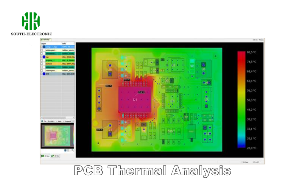
Ignoring vias can overheat chips silently. One design without vias hit 90°C in minutes—thermal vias dropped it to 65°C.
Vias act like heat pipes, pulling heat to other board layers or copper planes. Without them under bottom-mounted cooling, heat traps near components, escalating failure risk exponentially.
Vias as Thermal Superhighways
Vias turn your PCB into a 3D radiator. Their plating thickness and arrangement dictate efficiency:
| Via Factor | Impact on Cooling | Design Tip |
|---|---|---|
| Density (number/cm²) | Higher density = quicker heat spread | Place 6-8 vias/mm² for SMD components |
| Fill Material | Copper filler boosts conduction by 35% vs air | Use resin fill for cost savings |
| Pad Size | Wider pads reduce thermal resistance | Expand pads beyond component footprint |
| Depth | Partial vias leave heat islands | Route to inner ground planes if present |
In high-power designs, I use concentric rings of vias around hot zones. Combine them with copper planes to amplify heat dissipation. Remember—stackup material matters too. FR4 limits effectiveness; ceramic substrates work better.
Why Do Heatsinks Keep Failing?
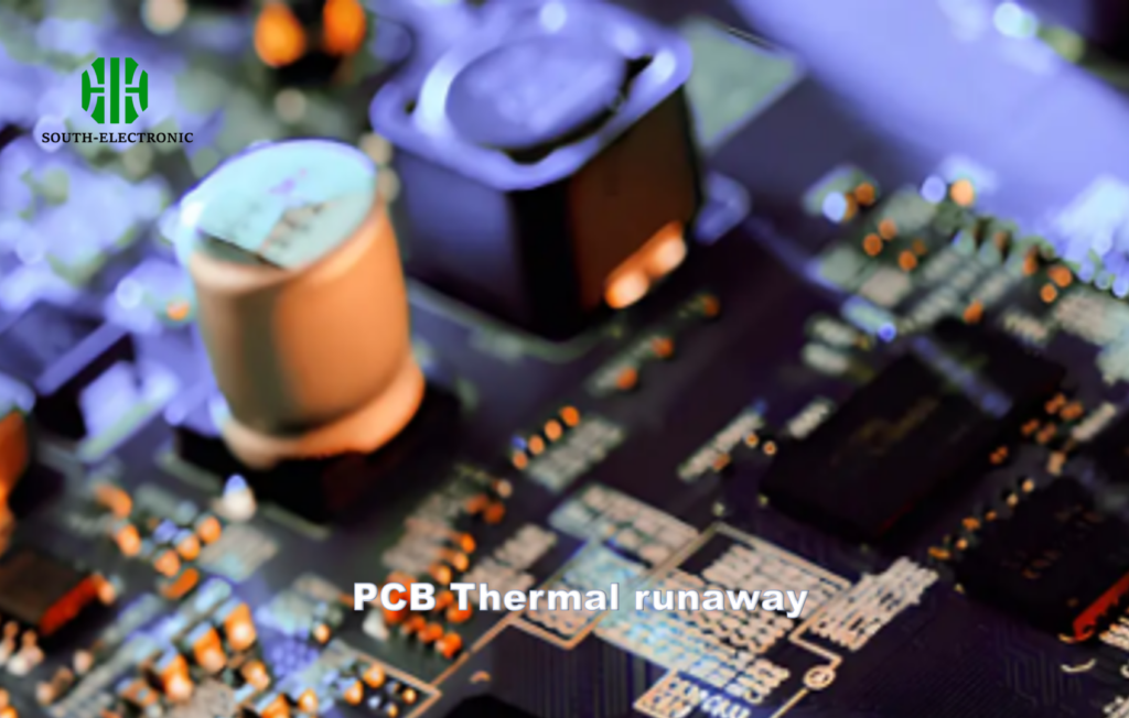
A failed heatsink killed my drone’s controller mid-flight. Root cause? Poor TIM application allowed gaps to form.
Heatsinks fail from TIM breakdown, inadequate airflow, or material incompatibility. Over 70% of failures trace back to thermal paste drying or attachment loosening due to thermal cycling stress.
Breaking Down Recurring Failure Points
Preventing failure means understanding these three enemies:
| Failure Mode | Why It Happens | My Prevention Strategy |
|---|---|---|
| TIM Degradation | High temps evaporate binders | Select silicone-free pastes above 200°C |
| Vibration Loosening | Poor mounting in mobile devices | Test clips/glues under simulated drops |
| Material Corrosion | Dissimilar metals + moisture | Match coefficients of expansion (e.g., copper-on-copper) |
| Fin Clogging | Dust buildup in compact designs | Use vertical fins + 5mm gap around vents |
I run thermal cycles during prototyping to expose weaknesses. For example, aluminum heatsinks flex during heating—using flexible pads avoids cracks. Never skip TIM tests: apply dots, lines, or spreads to test coverage thoroughly first.
Conclusion
Match heatsinks to your PCB’s needs by testing materials, attachments, and vias. Prevent failure through careful planning—your circuits will thank you.

