
Stuck on removing that delicate PCB connector? Fear damage to the board or pins? Removing connectors incorrectly is a guaranteed path to broken circuits. Don’t risk destroying valuable components or delicate traces on your board with the wrong approach.
Safely remove PCB connectors[^1] by first identifying their type and locking mechanism[^2]. Use precise tools like soldering irons, desoldering pumps, or wick for through-hole types. Apply gentle leverage near the housing for direct board mounts. Avoid forcing it; patience and the right technique prevent costly damage.
Knowing how to pull something off is simple. But safely removing different components like PCB connectors needs deeper knowledge. Understanding exactly what you’re dealing with is crucial first step before applying any method. Let’s explore the different connectors you might face.
What Are the Different Types of PCB Connectors?
Faced with a confusing mass of pins and plastic? Not all circuit board connector types release the same way. Different designs require specific techniques. Applying the wrong method can snap plastic housings or bend pins instantly.
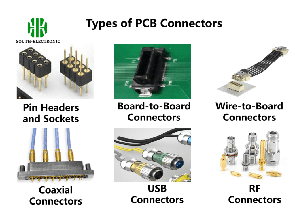
PCB connectors are grouped by their connection style and mounting. Major types include wire-to-board connectors, board-to-board connectors, headers and sockets, edge card connectors, and I/O connectors. Each type possesses a distinct locking mechanism crucial for safe removal.
Critical Connector Features for Removal
Understanding the mechanics is vital. Their locking method dictates the removal tool and force required. Consider these key aspects:
| Connector Feature | Why It Matters for Removal | Tools to Consider |
|---|---|---|
| Locking Mechanism | Defines how it’s secured; can clip, latch, friction fit, or solder. | Flush cutters, plastic spudgers |
| Through-Hole (TH) vs Surface Mount (SMD) | TH connectors need desoldering each pin. SMD connectors attach only via pads on the surface. | Soldering iron, desoldering pump/wick |
| Pitch & Pin Count | Finer pitch/higher pin count require more care during removal. | Precision tweezers |
| Housing Material | Brittle plastic cracks easily under prying force. | Heat gun (low temp), plastic pry tools |
The locking mechanism is your primary concern. Edge cards typically slide out when unlocked. Friction-fit headers demand pulling straight up with even force. ZIF (Zero Insertion Force) connectors feature a lever that disengages pins without force. Identifying this before grabbing tools protects your connector board and its components. Never just pull or pry randomly – locate the latch or release clip. For soldered connections like many through-hole connectors[^3], desoldering is mandatory; heating all pins simultaneously prevents damage caused by uneven stress. Always support the connector board underside with your hand to prevent flexing during any removal attempt.
PCB Connector Specifications Decoded
Ever grabbed specifications sheet and felt puzzled? Terms like pitch, current rating, mating cycles seem crucial for selection, but they also guide removal. Knowing specs prevents forceful removal mistakes damaging the connector board.
Key PCB connector specs impacting removal include the termination type[^4] (solder, press-fit, solderless), pitch (space between pins), current rating (affects pin robustness), housing material[^5] properties (durability/heat tolerance), and mating/un-mating force[^6] specification. High mating force likely means a strong locking mechanism requiring specific release.
Interpreting Specs for Safer Disconnection
Specifications translate into practical removal instructions. Let’s break the connection:
| Specification | Removal Indicator | Safe Removal Action |
|---|---|---|
| Termination Type | Solder: Need desoldering. Press-fit: Needs pulling tool or gentle leverage often with twisting. | Desoldering tools / Dedicated press-fit puller |
| Pitch Size | Smaller pitch = finer pins. Higher risk of bending. | Use magnifying glass and precision tools. |
| Mating Force | Indicates lock strength. Higher force connectors often need unlocking before extraction. | Find release lever/latch first. |
| Housing Material | FR4 brittle? Thermoplastic flexible? Affects prying method resistance. | Use non-marring pry tools (plastic/nylon) |
Always check the rated un-mating force or "extraction force" specification if available. This tells you how hard it should be to remove it. Significantly more force means you probably missed the lock or release. For through-hole or press-fit terminations, understand that pins are mechanically anchored. Desoldering releases solder bonds, while press-fit pins rely on interference friction. Apply force near the connector housing itself, never on wires or thin pins. Leverage tools only against sturdy, non-critical parts of the connector board. If pins remain stuck after release, check for hidden secondary locks or residue adhesive – a common issue in sealed connectors requiring careful scraping. Remember, the circuit board connector type details dictate the method.
What is a Wire-to-Board Connector?
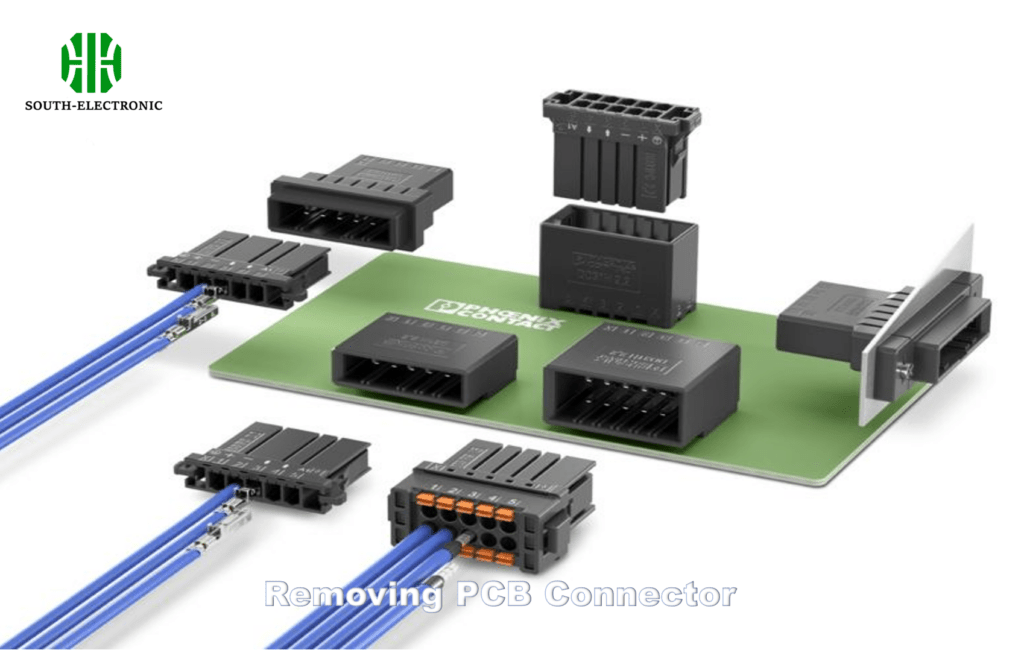
Look closely at a PCB. See where wires plug into the board? That’s usually a wire to board connector. This circuit board connector type links individual wires to terminals on the printed circuit board. They’re everywhere, in everything.
A wire-to-board connector[^7] consists of a housing (the plastic part mounted on the PCB) and terminals (metal crimp or IDC contacts) attached to wires that plug into it. Common types include Molex KK[^8], JST PH, XH, dupont headers. Locking involves simple friction latches, clips, or levers.
Safely Removing Wire-to-Board Connections
As the most common interface for external cabling, safe removal is frequent. Follow these structured steps:
- Identify Lock Type: Find the lock mechanism. Is it small plastic tabs? A side latch? A flip lever? Pressing, pinching, or flipping this component releases the wire harness. Never pull without releasing.
- Apply Targeted Pressure: Once the lock is disengaged, hold the plastic connector body firmly. Pull straight out along the axis of pin insertion. Avoid pulling wires.
- Tool Assistance: If stuck, gently insert a thin plastic tool near the housing seam. Apply minimal prying force. Metal tools scratch and short! Use plastic spudgers or specialized leverage tools designed for connector boards. Apply pressure only against the sturdy connector housing, never on the pins or socket body on the circuit itself.
- Worst Case Scenario: If fused or glued, apply focused low heat carefully. Avoid melting plastic. Use hot air stations carefully with low airflow and temperature. Pre-heat surrounding board area to reduce thermal shock. Use kapton tape to shield adjacent parts. A fine solder tip can sometimes apply local heat if one pin’s solder joint[^9] holds it strangely. Desolder that specific joint through the housing opening if possible.
Using force on the wires pulls the crimped terminal out of the housing. This is a common failure. Focus pressure near the plastic connector housing body. If pulling the mating end, hold both sides of the connector board to prevent stressing solder joints. Patience and precise tool placement near the mechanism is key for every connector board removal, especially wire-to-board types.
Conclusion
Removing PCB connectors safely requires identifying the specific type and its lock first, then using correct tools with patience. Remember: avoid force, understand the connector, protect the board. Prevent damage.
[^1]: Understanding the various types of PCB connectors is essential for safe removal and preventing damage. Explore this resource for detailed insights.
[^2]: The locking mechanism is crucial for safe removal of PCB connectors. Learn more about it to avoid damaging your components.
[^3]: Removing through-hole connectors requires specific techniques to prevent damage. Discover best practices to ensure safe removal.
[^4]: Understanding termination types is crucial for safe disconnection and preventing damage during removal. Explore this link for detailed insights.
[^5]: The housing material impacts the removal process significantly. Learn more about how to choose the right tools for different materials.
[^6]: Mating force is key to understanding how to safely unlock and remove connectors. This resource will enhance your knowledge on the topic.
[^7]: Explore this link to gain a deeper understanding of wire-to-board connectors, their types, and applications in electronics.
[^8]: Learn about Molex KK connectors, their features, and why they are widely used in various electronic devices.
[^9]: Discover best practices for soldering joints in PCB connectors to ensure reliable connections and prevent failures.


