
Frustrated with circuit failures? Your diode might be faulty. I’ve burned three diodes before learning this simple test. Let me show you how to avoid the same mistake.
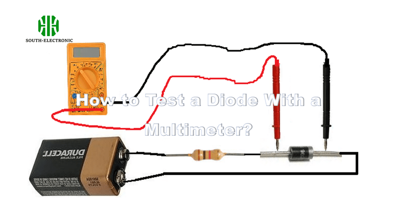
To test a diode, set your multimeter to "diode mode[^1]." Connect the red probe to the anode (positive side) and black to the cathode (negative side). A working silicon diode shows 0.6-0.7V. Reverse the probes—you should see "OL" (open loop).
Understanding diode testing saves hours of troubleshooting. Let’s explore the key steps and common pitfalls in detail.
How Do You Use a Multimeter’s Diode Test Mode to Check a Diode?
Wasting time on guesswork? Multimeters have a diode-specific mode for a reason. Many users skip this step and get unreliable results.
The diode test mode sends a small current through the component. It measures the voltage drop to determine if the diode works. Always start here before using resistance modes.
)
Three-Step Testing Process
- Set the dial: Look for the diode symbol (→|) on your multimeter
- Probe placement:
- Red → Anode
- Black → Cathode
- Interpret results:
- 0.6-0.7V = Good forward bias
- OL = Working reverse bias
Common Mistakes Table
| Error | Consequence | Solution |
|---|---|---|
| Using resistance mode | Inconsistent readings | Switch to diode mode |
| Touching probe tips | Body resistance skews results | Use alligator clips |
| Testing while powered | Damaged multimeter | Disconnect from circuit |
I once tested a diode in resistance mode and got 0Ω both ways. Only when I used diode mode did I realize it was blown open.
How Can You Identify the Anode and Cathode of a Diode Using a Multimeter?
Tired of squinting at tiny symbols? Even experienced techs mix up diode polarity sometimes.
No markings? Use your multimeter. A functional diode allows current flow only when probes match its anode-cathode orientation[^2].
)
Identification Methods
-
Visual inspection
Look for:- Cathode stripe (black/silver line)
- Dot near anode
- Longer anode lead in new diodes
-
Live testing
Connect randomly:- If you get 0.6V: Red probe = Anode
- If "OL": Reverse the probes
Diode Polarity Indicators Table
| Indicator Type | Appearance | Reliability |
|---|---|---|
| Cathode stripe | Painted band | 95% accurate |
| Lead length | Anode longer (new diodes) | 80% accurate |
| Case shape | Flat edge at cathode | 60% accurate |
During my internship, I memorized this rhyme: "Striped side strict, red probe picks positive."
How to Tell If a Diode Is Faulty: Key Signs of a Bad Diode?
Random circuit shutdowns? A bad diode often acts like a silent saboteur. Learn these surefire failure symptoms.
A shorted diode shows low voltage both ways (0.4V forward and reverse). An open diode reads "OL" in both directions.
)
Failure Modes Explained
-
Shorted diode
- Acts like a wire
- No voltage regulation
- Causes circuit overloads
-
Open diode
- Blocks all current
- Breaks circuit continuity
- Leads to dead systems
Diode Failure Symptoms Table
| Symptom | Forward Bias Reading | Reverse Bias Reading |
|---|---|---|
| Healthy diode | 0.6-0.7V | OL |
| Shorted diode | 0.3-0.4V | 0.3-0.4V |
| Open diode | OL | OL |
When my car alternator died last year, it had three shorted diodes. The multimeter showed 0.4V in both directions.
Why Does My Multimeter Show Unexpected Readings, and How Do I Fix It?
Getting 2.8V on a silicon diode? Don’t panic. Multimeter quirks cause 80% of abnormal readings.
Improper settings, bad probes, or stray voltages cause most issues. Always verify these three first.
)
Troubleshooting Guide
-
Check mode
Are you actually in diode mode? Resistance mode gives erratic results. -
Clean probes
Dirty tips add resistance. Scrub with alcohol and steel wool. -
Isolate diode
Test it alone—other components in-circuit can skew readings.
Common Issues Table
| Unexpected Reading | Likely Cause | Fix |
|---|---|---|
| 0.1-0.3V | Probe reversal | Swap red/black probes |
| 1.2V+ | LED being tested | Normal for LEDs |
| Fluctuating values | Loose connections | Use clip leads |
My student once panicked over 2.5V readings. Turns out he was testing a Zener diode meant for 3V operation.
Conclusion
Master diode testing to diagnose circuits faster. Remember: diode mode first, verify polarity, and isolate components. Your multimeter is your best ally against sneaky component failures.
[^1]: Understanding diode mode is crucial for accurate testing. Explore this resource to enhance your multimeter skills and avoid mistakes.
[^2]: Knowing the anode-cathode orientation is vital for circuit design. Check this resource for comprehensive guidance.


