
Industrial PCBs fail unexpectedly in harsh environments. Corrosion, vibration, and temperature extremes challenge even robust designs. What separates reliable industrial boards from those that malfunction under stress?
Industrial PCB production combines durable materials (FR-4 HT, metal-core) with IPC Class 3 standards and automated quality checks. From design-for-manufacturing simulations to final conformal coating, every step prioritizes reliability for aerospace, automotive, and heavy machinery applications.
While materials matter, surviving industrial environments requires more than sturdy substrates. Let’s dissect how modern workflows turn raw fiberglass and copper into mission-critical PCBs.
How Does the Industrial PCB Manufacturing Process Work from Design to Final Assembly?
A medical device PCB failed after 200 thermal cycles. The culprit? Inadequate via plating. Industrial manufacturing eliminates such flaws systematically.
The industrial PCB process spans 12+ stages: CAD design validation, multilayer lamination, laser drilling, AOI testing, and functional verification. Automated traceability ensures compliance with MIL-PRF-31032 or ISO 9001 standards.

Critical Phases in Industrial PCB Production
| Stage | Industrial Requirement | Consumer PCB Equivalent |
|---|---|---|
| Material Selection | High-Tg FR-4, ceramic-filled PTFE | Standard FR-4 |
| Drilling Tolerance | ±0.025mm (laser) | ±0.05mm (mechanical) |
| Plating Thickness | 25μm+ copper, ENIG finish | 15μm copper, HASL finish |
| Testing Rigor | 100% electrical + thermal shock tests | Sample-based testing |
Industrial designs start with DFM (Design for Manufacturing) checks. Simulation tools like Mentor Xpedition predict thermal stress points. Multilayer boards undergo sequential lamination – 6-8 layers for motor control units, up to 24 layers in avionics. Post-etching, automated optical inspection (AOI) compares boards against golden samples. Final assembly uses solder pastes rated for -55°C to 150°C operational ranges.
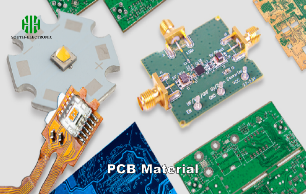
What Materials and Technologies Are Essential for High-Performance Industrial PCBs?
A drilling rig’s control board failed in the Arctic. Standard FR-4 cracked at -40°C. Material science makes all the difference.
Industrial PCBs require:
- Substrates: Rogers 4350B for RF, aluminum-core for thermal management
- Conductive inks: Silver-palladium for flexible heaters
- Coatings: Parylene C (8-12μm) for chemical resistance
Material Selection Matrix
| Application | Base Material | Key Property | Thickness Range |
|---|---|---|---|
| High-frequency RF | Rogers RO4003C | Low dielectric loss | 0.2mm – 3.2mm |
| High-power motor drives | Aluminum-backed IMS | 8-12 W/mK thermal conductivity | 1.6mm – 5.0mm |
| Oil & gas sensors | Polyimide flex | 2% moisture absorption | 0.1mm – 0.3mm |
Embedded passive components (resistors, capacitors) reduce solder joints – a common failure point. For automotive ADAS systems, AISM-390 grade prepreg ensures stable impedance across 77GHz radar frequencies. Conformal coating robots apply acrylic or silicone films 3x faster than manual methods, critical for high-mix production.
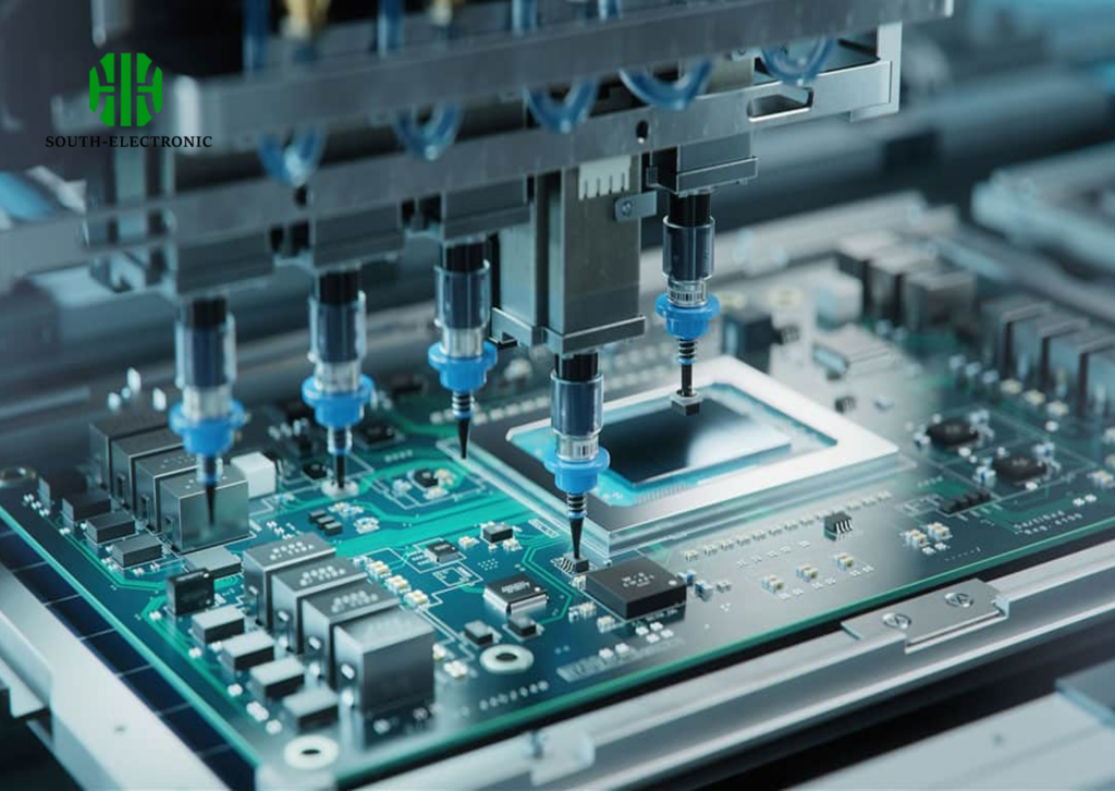
How Can Automation and IoT Improve Efficiency in Industrial PCB Production?
A factory lost $220k/month from reworking poor solder joints. IoT-enabled paste dispensers slashed defects by 63%.
Automated optical inspection (AOI) with neural networks detects 0.1mm solder bridges. IoT-enabled machines share real-time data: stencil pressure, reflow oven zones (±1°C), and pick-and-place accuracy (±0.01mm).

Automation Impact Analysis
| Process | Manual Approach | Automated + IoT Solution | Cycle Time Improvement |
|---|---|---|---|
| Solder Paste Inspection | 5min/board (human) | 45sec/board (3D SPI) | 85% faster |
| Component Placement | 3,200 CPH (operators) | 25,000 CPH (multistage bots) | 680% faster |
| Traceability | Paper-based logging | Blockchain-enabled digital twin | 99.97% accuracy |
Predictive maintenance on CNC drillers uses vibration sensors to forecast bearing wear 2 weeks in advance. Cloud-based ERP systems auto-adjust procurement – when IoT detects increased FR-4 usage, it orders substrates before stock depletes.
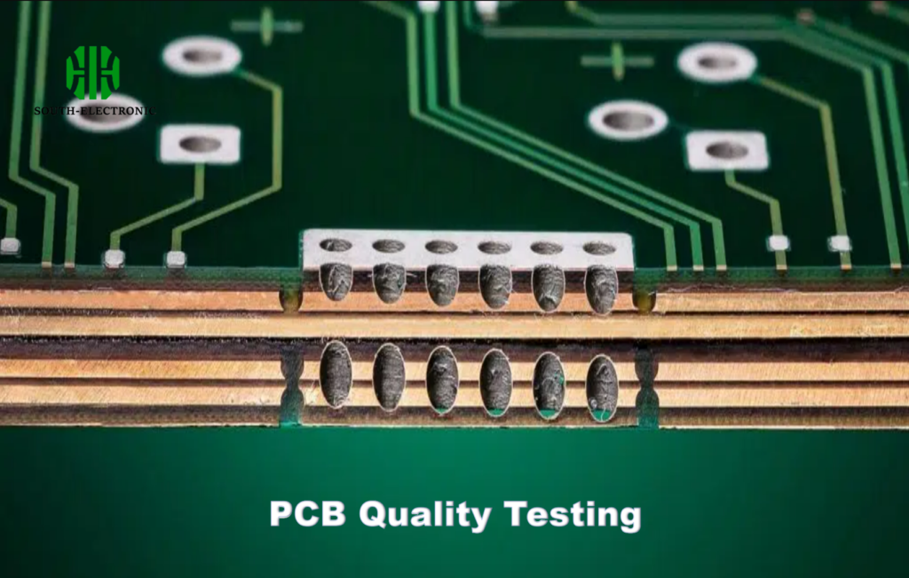
What Quality Control Strategies Ensure Reliability in Industrial PCB Manufacturing?
A satellite PCB passed initial tests but failed in orbit. Missing microvoids in BGA joints were invisible without X-ray.
Industrial QC combines:
- Electrical: Flying probe tests at 150°C
- Mechanical: 6-axis vibration testing (5-2000Hz)
- Environmental: 85°C/85% RH for 1000 hours
Reliability Verification Stack
| Test Type | Standard | Industrial PCB Parameters |
|---|---|---|
| Thermal Cycling | IPC-9701 | -55°C to +125°C, 1000 cycles |
| HALT (Highly Accelerated Life Test) | MIL-STD-810G | 40g vibration, rapid temp ramps |
| CAF (Conductive Anodic Filament) Resistance | IPC-650 | 65V/mm, 96hrs humidity exposure |
AOI machines with 10μm resolution scan every via. Cross-sectional microsectioning checks plating uniformity. For aerospace boards, ion chromatography verifies ionic cleanliness (<1.56 μg/cm² NaCl equiv). Suppliers like TT Electronics use robotic sample testing – 0.01% defect rate vs industry’s 0.1% average.
Conclusion
Industrial PCB success hinges on merging cutting-edge materials (high-Tg laminates), smart automation, and exhaustive testing (1000+ thermal cycles). The real game-changer? IoT-driven traceability from pcb board prototype to final assembly.

