
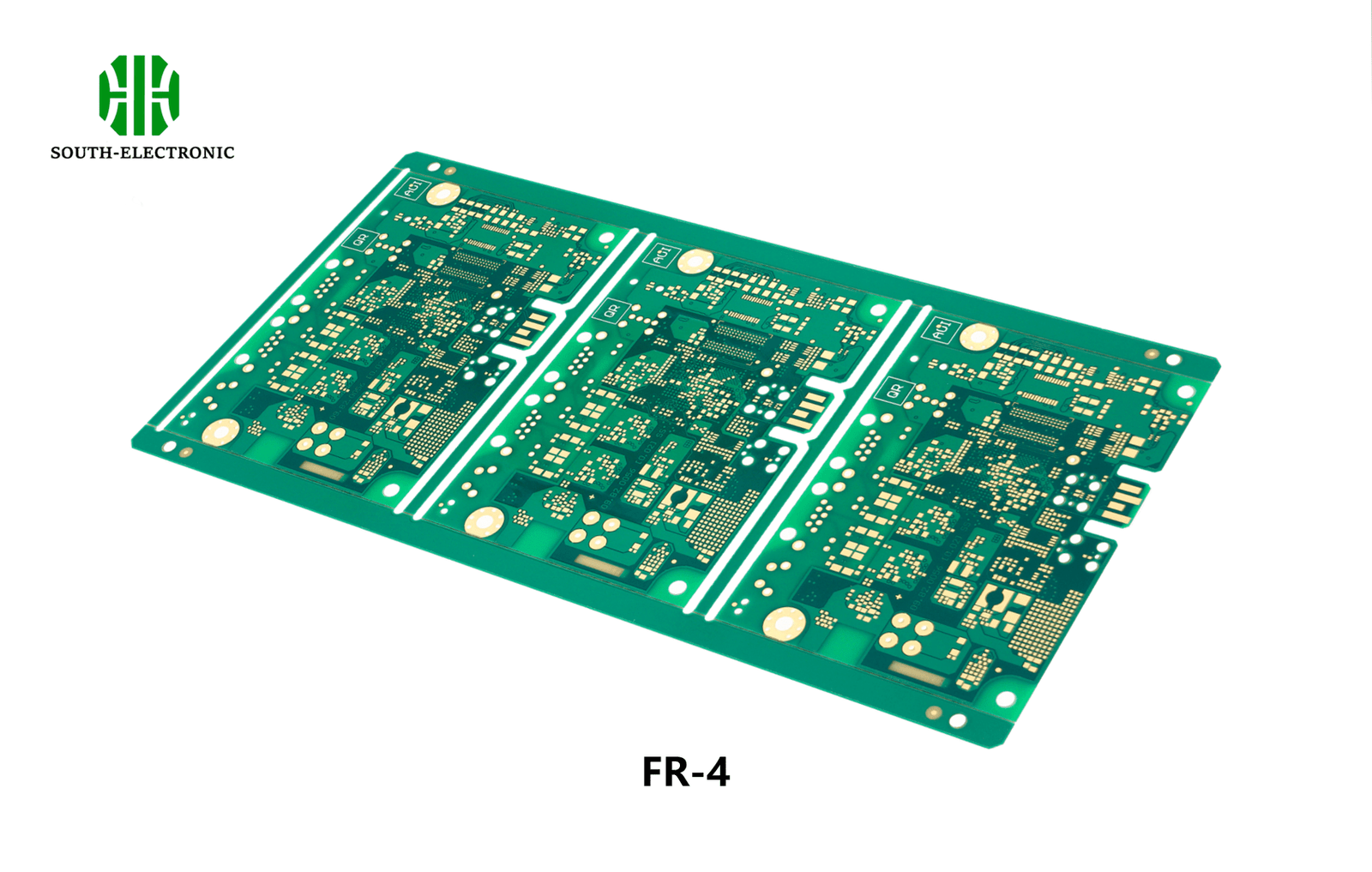
Facing signal delays in your circuit design? Your FR-4 choice might be the hidden culprit. I see engineers frustrated when designs underperform. But FR-4 can still work if you know its limits.
Standard FR-4[^1] handles MHz-range signals well, especially for short traces under 1GHz. Its higher cost efficiency helps budget projects. But beyond 5GHz or long routes, dielectric losses[^2] degrade performance. Careful routing and shielding become essential.
Before abandoning FR-4 entirely, let’s dissect its real-world suitability through key technical questions. Your project demands might still match its strengths.
What’s the ideal thickness & layer count for an FR-4 board?
Signal noise ruining your prototype? Incorrect board thickness often amplifies interference. Start with layer configuration first.
A 4-layer FR-4 stackup[^3] balances cost and performance for moderate speed designs. Choose 0.062"-0.125" thickness using ground plane separation for best impedance matching in 1GHz designs – isolate noisy/digital sections
- 10+ layers: Reserved for RF systems with strict attenuation limits
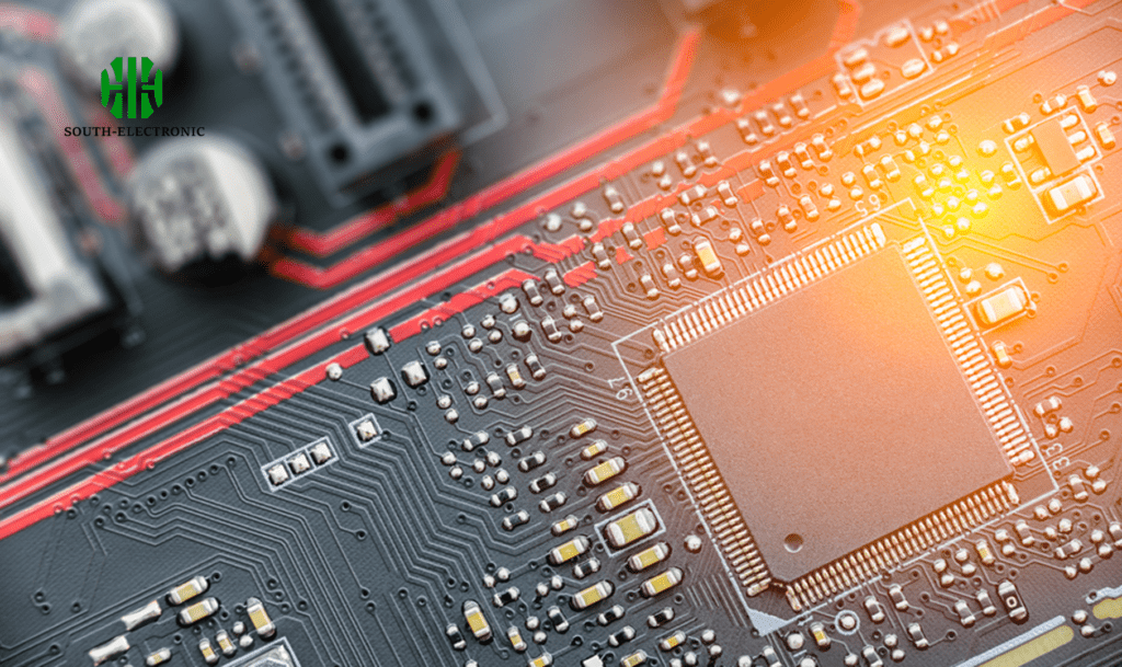
Thermal dissipation must match component heat. FR-4’s low conductivity (0.25W/mK) becomes critical with BGAs or processors. Mitigate risks through:
| Parameter | Low-Risk Zone | Mitigation Technique |
|---|---|---|
| Power Density | <0.5W/cm² | Copper plane heat spreading |
| Trace Current | <5A per layer | Thermal vias under hot components |
| Ambient Temp | 3A power traces |
Thermal conductivity gaps cause cascade failures. When MOSFETs hit 100°C, FR-4 substrates expand unevenly. This warps boards and cracks solder joints. I’ve salvaged designs by:
- Reducing copper planes below component pads
- Adding 0.5mm thermal relief gaps
- Switching to high-Tg FR-4[^5] (>170°C rating)
EMI containment[^6] requires structural adjustments. FR-4’s permeability allows interference coupling. Guard traces and shielding cans help, but ground stitching proves vital:
| Frequency Range | Stitching Via Spacing | Shielding Effectiveness |
|---|---|---|
| 10GHz | Active EMI filters | <10dB reduction |
For satellite systems I worked on, FR-4[^1] RF boards required Faraday cage enclosures.
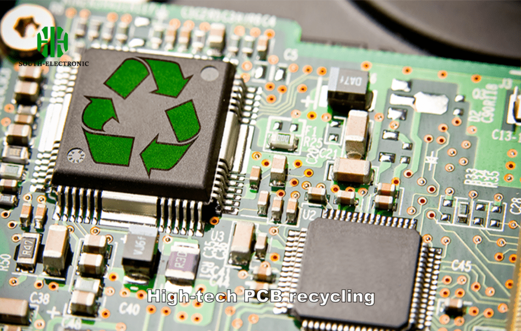
Are FR-4[^1] boards environmentally friendly?
Burned circuit boards piling up in your lab? Traditional FR-4[^1]’s environmental impact alarms every eco-conscious engineer.
Standard FR-4[^1] uses brominated flame retardants classified as persistent pollutants. End-of-life recycling remains challenging due to toxic metal-leach risks during disposal.
Sustainable Material Alternatives in Modern Electronics
Three strategies reduce environmental harm while retaining functionality.
Halogen-free laminates offer direct replacements. Manufacturers now produce FR-4[^1] using phosphorus instead of bromine. Performance matches standard grades. Though costs rise 8-12%, RoHS compliance eliminates disposal issues – a switch I support.
Thermal stability upgrades extend lifespan. Moisture absorption causes delamination. Hydrolysis-resistant High-Tg FR-4[^1] variants perform better in humid environments:
| Property | Standard FR-4[^1] | Eco-HighTg FR-4[^1] |
|---|---|---|
| Recyclability | 15% | 60% |
| Moisture Resistance | Low | High (CAF-resistant) |
| Decomposition Temp | 325°C | 385°C |
Design approaches shrink footprint. My experiments show:
- Panel utilization over 85% reduces scrap
- Lead-free HASL finishing cuts toxic cadmium
- 4-layer boards use 25% less laminate than 6-layer
Still, no perfect solution exists – I balance cost, performance and eco-impact case-by-case.
Conclusion
FR-4[^1] suits MHz-speed designs with thermal protections. For extreme GHz performance, low-loss materials justify their cost. Always match specs to your project’s true demands.
[^1]: Explore the pros and cons of FR-4 to understand its suitability for your specific circuit design needs.
[^2]: Learn about dielectric losses and their impact on circuit performance, especially in high-frequency applications.
[^3]: Discover the benefits of using a 4-layer FR-4 stackup for balancing cost and performance in your projects.
[^4]: Understanding signal integrity is crucial for optimizing your PCB designs and ensuring reliable performance.
[^5]: Learn about high-Tg FR-4 and its advantages for applications requiring higher thermal stability.
[^6]: Explore effective EMI containment strategies to enhance the performance of your circuit boards.


