

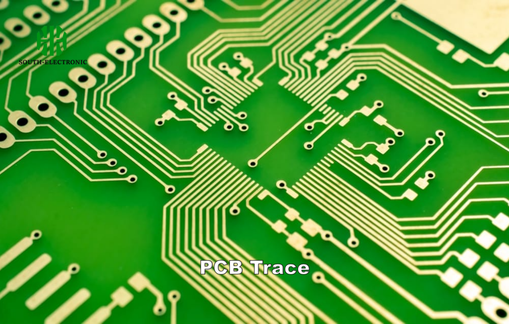
Printed circuit boards power modern electronics—but how do manufacturers verify their electrical integrity[^1] before mass production? Defective PCBs lead to costly recalls and project delays. Flying probe testing solves this quality challenge with robot-powered precision.
Flying probe testing[^2] uses robotic arms equipped with electrical probes to automatically check PCB connections and components. Unlike traditional methods requiring custom fixtures, it verifies continuity, resistance, and insulation errors through programmed test sequences.
Let’s dissect how this agile inspection method detects flaws while saving costs—especially for prototypes and small batches—and why its optical alignment ensures lab-grade accuracy.
What Exactly Is Flying Probe Testing and How Does It Ensure PCB Quality?
Imagine building a prototype PCB, only to find a short circuit buried in layer 4 after assembly. Flying probes prevent such nightmares through systematic quality control.
Electrically-driven probes move across the PCB’s surface using pre-programmed coordinates, testing connections by physically contacting pads and traces. This checks for manufacturing defects like opens, shorts, and incorrect component values.
)
Three-Stage Verification Process
Flying probes validate boards through sequential electrical tests:
| Test Stage | Parameter Measured | Defects Detected |
|---|---|---|
| Connectivity | Continuity between nodes | Open circuits, missing parts |
| Resistance | Ohmic values of paths/traces | Thin copper traces, poor soldering |
| Insulation | Isolation resistance | Short circuits between circuits |
For multi-layer boards, probes execute high-voltage dielectric tests between adjacent planes. In a recent project, this method identified a 0.5mm solder bridge beneath a BGA chip that escaped manual inspection.
Why Is Flying Probe Testing More Cost-Effective Than ICT for Prototypes?
Custom test fixtures for ICT (In-Circuit Testing[^3]) can cost $10,000+ and require weeks to fabricate—a barrier for prototyping.
Flying probe testing eliminates fixture costs by using software-guided probes. It adapts to design changes instantly, making it 68% cheaper than ICT for batches under 100 units.
)
Breaking Down the Savings
Initial investment analysis for a 2-layer PCB prototype:
| Cost Factor | Flying Probe | ICT |
|---|---|---|
| Fixtures | $0 | $12,500 |
| Setup Time | 15 minutes | 3 weeks |
| Test Programming | $800 | $1,200 |
| Cost per Board | $8 | $22 |
ICT becomes viable only for volumes above 1k units. Automotive startups have reported saving $47k annually by switching to flying probes for EV controller prototypes.
What Circuit Parameters Can Flying Probes Measure in PCB Validation?
Modern flying probe systems go beyond basic pass/fail checks with parametric measurements rivaling benchtop instruments.
Flying probes can measure resistance (0.1Ω – 50MΩ), capacitance (5pF – 200μF), inductance (1μH – 1H), and diode forward voltage with ±1% accuracy. Advanced systems even perform in-circuit transistor gain testing.
)
Precision Testing Capabilities
Critical measurements for IoT device PCB validation[^4]:
| Component | Test Parameter | Tolerance | Probe Method |
|---|---|---|---|
| Power Plane | DC Resistance | ±0.5Ω | 4-Wire Kelvin |
| Decoupling Cap | ESR @ 100kHz | 20% | AC Impedance |
| Crystal Osc. | Load Capacitance | 5pF | Frequency Sweep |
| USB Data Line | Insulation >100MΩ | 90s dwell | 50V DC Test |
During a medical device audit, probe-measured capacitor ESR values matched laboratory LCR meter readings within 3%—validating production-grade accuracy.
How Does Automated Optical Alignment[^5] Improve Testing Accuracy?
Human vision can’t reliably align micron-scale probes with PCB pads. Automation solves this through machine vision precision.
High-resolution cameras scan PCB fiducial markers to map testing coordinates within 10μm accuracy. Probes self-correct positions using real-time optical feedback, eliminating manual calibration errors.
)
Alignment Workflow Comparison
Traditional vs automated probe positioning:
| Step | Manual Method | Automated Optical |
|---|---|---|
| Board Loading | ±500μm tolerance | Vacuum-secured ±50μm |
| Fiducial Detection | Visual inspection | 25MP camera scan |
| Probe Approach | Hand-adjusted | Laser-guided XYZ motion |
| Contact Verification | Ohmmeter check | Force sensing (0.01N resolution) |
A drone manufacturer reduced false opens by 92% after implementing optical alignment—critical for 0.4mm-pitch QFN package testing.
Conclusion
Flying probe testing delivers agile, precise PCB validation without fixed tooling. From prototyping to low-volume runs, it balances cost and quality while adapting to evolving designs—a game-changer for hardware innovators.
[^1]: Learn about the methods used to ensure electrical integrity in PCBs, crucial for avoiding costly defects.
[^2]: Explore this link to understand the mechanics and benefits of flying probe testing in PCB manufacturing.
[^3]: Learn about In-Circuit Testing and its limitations compared to Flying probe testing, especially for low-volume production.
[^4]: Learn about effective PCB validation techniques to ensure reliability and performance in IoT devices.
[^5]: Explore how automated optical alignment enhances precision in PCB testing, reducing errors and improving efficiency.

