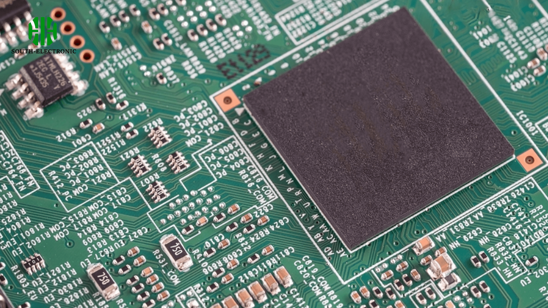
PCB Layout Service
South-Electronic
At South-Electronic, wespecialize in providing high-quality PCB layout services, ensuring reliability, durability, and improved performance for your products. Our custom designs are tailored to meet your unique project needs, carefully crafted to optimize performance and reliability. With eight advanced production lines, we guarantee fast processing and on-time delivery, no matter the size of your order.
Why Choose South-Electronic?
At South-Electronic, We follow strict quality control processes, ensuring every PCB meets the highest industry standards, helping you reduce maintenance costs and improve customer satisfaction. From design and prototyping to mass production, South-Electronic offers comprehensive solutions, simplifying your supply chain and reducing costs.
- Customized Design
Customized Design to Meet Your Unique Needs.
At South-Electronic, we understand that every project is unique. That's why our PCB layout services are customized to meet your specific requirements, ensuring that every detail is executed to your exact specifications. This will improve the performance and reliability of your products. - Guaranteed Satisfaction
You’ll appreciate the confidence that comes with working with an ISO9001 certified company.
We prioritize clear, transparent communication and hold ourselves to the highest standards, ensuring that your 8-layer PCBs not only meet but exceed your expectations for performance, durability, and precision. - One-Stop Service
When you choose us, you get a complete PCB solution from design and prototyping to mass production.
We offer a one-stop service, eliminating the complexity and cost of dealing with multiple suppliers. - Comprehensive Service
You get complete satisfaction with our wide range of equipment.
We have a wide range of PCB processing capabilities. From design to delivery, we have the equipment and processes to make sure your order is done right. - Fast Delivery
You stay on schedule with our fast turnaround times.
Our streamlined production ensures fast turnaround times, so you get your products when you need them, without delays.
Related Project We had Done
Customer Reviews
engineer
thank you, guys, the boards are really good, i am really happy to receive my boards, the components are perfect!
Operation Manager
South-Electronic is my first PCBA supplier in China. The service and quality are excellent, and the after-sales support is also very impressive. Good Job!
Common Questions
Most Popular Questions
At South-Electronic, you'll get continuous tech support from our experienced engineers and tech experts. They're available to advise and resolve any issues that come up during the design and production phases. We communicate through regular updates and direct access, so you can be sure your project is on track.
Yes, South-Electronic is great at doing custom designs to meet your unique project specs. We work closely with you to customize every aspect of the PCB layout, so it meets your exact needs and improves your product's performance and reliability.
We're usually able to turn things around quickly at South-Electronic, thanks to our efficient processes and advanced production lines. While the timeline can vary depending on the complexity of your project and how big your order is, we're committed to meeting tight schedules and getting things to you on time.
We have strict quality control procedures in place throughout the entire production process. South-Electronic follows the best industry standards, doing thorough testing and inspections at every stage to make sure every PCB we make is of the highest quality and reliability.
We have a strong production capacity at South-Electronic, with eight advanced production lines that let us handle both small and large-scale orders. Our operations are flexible and can scale up based on what your project needs, so we can handle large volumes if that's what you need.
Our production lines are equipped with the latest technology and state-of-the-art equipment to ensure precision and efficiency. That includes automated machinery and advanced tools that let us maintain high quality while also speeding up production times.
Send us a message
The more detailed you fill out, the faster we can move to the next step.
The Complete Guide for PCB Layout
Contents
Chapter 1
Introduction to PCB Layout
PCB layout is a big deal in the world of electronics. It’s the backbone of almost all electronic devices, from simple gadgets to complex machinery. If you’re an engineer or a hobbyist who wants to create efficient and reliable electronic systems, you need to know about PCB layout.
What is PCB Layout?
PCB layout is the process of designing the physical arrangement of components and electrical connections on a printed circuit board. That means you’re putting electrical components in a logical and efficient configuration and then routing the electrical connections between them.
A PCB usually has multiple layers, including copper layers for the circuit paths, a substrate layer for insulation, and a solder mask layer for protection. This layering allows you to miniaturize circuits, which means you can fit advanced electronics into small spaces.
Here are some key aspects of PCB layout:
- Component Placement: Figuring out where to put components so they work well and fit.
- Trace Routing: Designing the physical paths that electrical signals will follow.
- Design Rules Check (DRC): Making sure your layout follows manufacturing capabilities and best practices.
- Signal Integrity: Keeping electrical signals good as they go through the board.
- Thermal Management: Dealing with the heat that components generate so they don’t get damaged or fail.
Why PCB Layout is Important in Electronics
PCB layout is important in electronics for a bunch of reasons:
- Reliability and Functionality: A good PCB layout means your electronic devices work without failing. A good layout minimizes places where things can go wrong and interfere with each other, which makes your device more reliable.
- Size and Compactness: With a good PCB layout, you can pack electronic components into smaller areas. That means you can make smaller devices that do more stuff, like smartphones and wearables.
- Cost Efficiency: If you optimize your PCB layout, you can save money when you manufacture your boards. An efficient layout means you use less material and get more boards out of a production run, which lowers your costs.
- Performance Optimization: A well-thought-out PCB layout minimizes delays and interference with signals, which is important for high-speed and high-frequency applications. That means your stuff works better and is more efficient.
- Thermal Management: A good layout helps you deal with heat by putting components in the right places and designing good heat dissipation paths. That means your device will work well and be safe for a long time.
- Scalability and Flexibility: A good PCB layout makes it easier to make changes and updates. That’s important when you’re doing a bunch of design iterations and when you’re scaling up production because you have a hit on your hands.
So, PCB layout is a big deal. It affects how well your stuff works, how much it costs to make, and how big it is. If you want to make cool, reliable electronic products, you need to know about PCB layout.
Chapter 2
Understanding PCB Design Basics
PCB design forms the core of creating efficient and reliable electronic systems. By grasping the basics of PCB design, engineers and designers can create circuits that meet specific performance, size, and cost criteria.
Components of PCB Design
When designing a PCB, several key components and concepts need to be considered to ensure an effective layout:
Substrate:
- The substrate is the base material of the PCB, providing mechanical support for the entire board. It is usually made from fiberglass (FR4) and acts as an insulating layer between the board and its components.
Copper Layers:
- Copper layers are where the electrical circuits are etched. A PCB can have multiple copper layers for complex designs, with traces forming the pathways for electrical signals.
Solder Mask:
- This is a protective coating applied to the copper layers, preventing short circuits and protecting them from environmental damage. It gives PCBs their characteristic green color, though other colors are available.
Silkscreen:
- The silkscreen layer adds text and symbols to the PCB for identification of components, test points, and other indicators. It aids in assembly and debugging processes.
Traces and Pads:
- Traces are the conductive paths, akin to wires, that connect different components on the PCB. Pads provide the surface areas where components are soldered to the board.
Via:
- Vias are small holes that allow electrical connections between different layers of a multi-layer PCB. They are filled with conductive material to facilitate inter-layer connectivity.
Components:
- This includes all the electronic parts soldered onto the PCB, such as resistors, capacitors, microchips, connectors, and more. Proper placement and orientation of these components are critical for circuit functionality.
Design Rules and Constraints:
- These are the guidelines set to ensure the design is feasible for manufacturing and functions correctly under specified operating conditions. They include spacing, size, and electrical limitations.
Types of PCBs
PCBs come in various types, each suited to different applications and design requirements. Here are some common types:
Single-Sided PCBs:
- These have one copper layer and are the simplest type of PCB. They are cost-effective and easy to manufacture, making them ideal for low-density or simple circuits like calculators and power supplies.
Double-Sided PCBs:
- Featuring copper layers on both sides, double-sided PCBs allow for more complex circuits as components and routes can be placed on either side. They are commonly used in power monitoring, industrial controls, and automotive applications.
Multi-Layer PCBs:
- Composed of three or more copper layers, these PCBs are stacked with insulating layers in between. They are suitable for advanced technology products, such as computers and aerospace instrumentation, due to their capability to house complex circuits in limited space.
Rigid PCBs:
- These PCBs have a solid substrate material that does not flex. They are used in situations where the PCB must remain stable and retain its shape, such as in desktop computers and network infrastructure.
Flexible PCBs:
- Made of flexible plastic substrates, these PCBs can bend and fit into compact or irregular spaces. They are often used in wearables, mobile devices, and flexible electronics.
Rigid-Flex PCBs:
- Combining the characteristics of both rigid and flexible PCBs, these allow sections of the PCB to flex while the main board remains rigid. They are ideal for applications that require both flexibility and controlled durability.
High-Frequency PCBs:
- Designed to manage signals in the gigahertz range, these PCBs are used in applications like satellite and communication systems, where signal integrity at high frequencies is crucial.
Understanding these components and types is vital for anyone involved in PCB design, as it paves the way for creating efficient, cost-effective, and high-performance electronic systems.
Chapter 3
Essential PCB Layout Design Software
In the process of designing PCB layouts, having the right software tools is crucial. These tools not only streamline the design process but also help in simulating and testing the design before actual production. Using the correct PCB design software can significantly enhance accuracy, efficiency, and creativity in your projects.
Overview of Popular PCB Design Tools
Several PCB design tools are available, each catering to different requirements and levels of expertise. Here’s an overview of some widely-used PCB design software:
Altium Designer:
- Known for its comprehensive feature set, Altium Designer is favored by professional engineers for complex and large-scale projects. It offers robust library management and advanced simulation tools, making it suitable for high-end designs.
Eagle (Easily Applicable Graphical Layout Editor):
- One of the most popular tools among hobbyists and professionals, Eagle is recognized for its user-friendly interface and flexibility. It provides powerful editing options and a large library of components. Autodesk now owns it, enhancing its integration with other design tools.
KiCad:
- A free and open-source PCB design tool, KiCad is gaining popularity due to its capabilities that rival commercial software. It supports complex designs with multiple layers and offers strong community support for additional libraries and modules.
OrCAD:
- This tool is suitable for a wide range of projects from simple to complex. Known for powerful simulation capabilities, OrCAD is favored in academic and industrial environments, where in-depth electrical design precision is required.
Proteus:
- Proteus offers ease of use and is particularly popular for teaching, education, and beginner-level projects. It allows for visual simulation alongside PCB design, which helps in understanding circuit behavior before actual implementation.
DipTrace:
- Well-suited for creating easy-to-complex designs, DipTrace offers an intuitive interface and simplified workflow. It supports 3D previewing, which aids designers in visualizing the final product more accurately.
DesignSpark PCB:
- Aimed at both beginners and experienced designers, DesignSpark is free and offers unlimited pads and nodes. It features a large library and easy-to-learn interface, which makes it a go-to for less complex projects.
Chapter 4
PCB Layout Best Practices
If you want to create designs that perform well, are reliable, and can be manufactured easily, you need to know the best practices for laying out printed circuit boards (PCBs). Two of the most important aspects of PCB design that affect these factors are signal integrity and power distribution.
Designing for Signal Integrity
Signal integrity is about keeping electrical signals clean as they travel through a PCB. Poor signal integrity can cause data loss, noise, and circuits that don’t work right. Here are some of the best practices for good signal integrity:
- Keep Trace Lengths Short:Shorter traces have less resistance, less inductance, and less chance for signals to degrade. Keep high-speed signals as short as you can.
- Control Impedance:Design traces with controlled impedance, especially for high-frequency circuits, so you don’t get reflections and loss. Impedance matching makes sure signals get transmitted efficiently.
- Use Ground Planes Wisely:Solid ground planes give signals a reference point, reduce noise, and make the whole electrical system work better. They also help reduce electromagnetic interference (EMI).
- Keep Signals Separate:Keep high-speed signals away from low-speed or high-current signals so they don’t interfere with each other. Use ground traces or copper zones between different types of signals.
- Don’t Cross Vias:Too many vias can mess up signal flow and add inductance. Use fewer vias for important signals and keep the routes straight when you can.
- Route Differential Pairs Properly:For signals that go as differential pairs, keep the spacing and length of the pairs the same so the signals stay balanced and clean.
- Terminate Signals Correctly:Use the right termination techniques (like parallel or series resistors) to match the line impedance and keep signals from reflecting.
- Watch Signal Return Paths:Make sure the return paths for signals are direct and unbroken. Put ground vias near signal vias to make sure the return paths work well.
Layout Guidelines for Power Distribution
Good power distribution design is important for getting stable power to all the parts, reducing voltage drops, and making less heat. Here are some guidelines for good power distribution:
- Use Wide Power Traces:Wider traces or copper pours can carry more current with less resistance, so you get less voltage drop and less heat.
- Use a Dedicated Power Plane:A dedicated power plane lets you distribute power evenly and keeps the voltage from bouncing around. It also gives you a low-inductance path through the whole circuit.
- Use Decoupling Capacitors:Put decoupling capacitors close to the power pins of ICs to filter out voltage spikes and give instant power during fast events.
- Use a Star Topology for Branching:Use a star topology to branch power lines from a central point so you have less area for the current loops and less noise on the power and ground lines.
- Stitch Power and Ground with Vias:Use vias to connect power and ground planes so you have less inductance in the loops and good, solid ground paths.
- Avoid Ground Bounce:Don’t let different parts of the board that carry heavy current share the same ground path. That way, you don’t get dynamic voltage changes that mess up the ground.
- Think About Heat:Spread out the power components to manage heat. Use heat sinks or thermal vias for parts that make a lot of heat.
- Check Power Integrity:Use simulation tools to check power integrity so you know the voltage doesn’t go too far away from where it should be anywhere on the board.
By using these best practices in your PCB layout designs, you can get good signal integrity and good power distribution, which will make your electronic products work well in all sorts of situations.
Chapter 5
Component Placement Strategies
Proper component placement is a crucial step in PCB layout, directly influencing the board’s electrical performance, thermal management, and manufacturability. Implementing strategic component placement enhances the overall functionality and reliability of the circuit.
Importance of Strategic Component Placement
Signal Integrity:
- Strategic placement minimizes the length of signal paths, reducing potential delays, reflections, and noise, thereby enhancing signal integrity and performance.
Thermal Management:
- Efficient component placement aids in heat dissipation. Proper arrangement prevents overheating, ensures components operate within safe temperature ranges, and extends the lifespan of the board.
Ease of Assembly:
- Organized component placement simplifies the assembly process, reduces errors, and lowers production costs. Clear separation and logical arrangement enable automated assembly lines to work efficiently.
Reduced Electromagnetic Interference (EMI):
- Careful placement minimizes crosstalk and electromagnetic interference by maintaining optimal distances between components and providing effective grounding paths.
Maintenance and Testing:
- Designing with maintenance in mind allows for ease of access to critical components for testing and repairs, which is critical for complex or high-reliability applications.
Space Optimization:
- Strategic placement maximizes the use of available space, enabling miniaturization of electronic devices without sacrificing functionality.
Tips for Efficient Component Arrangement
Prioritize Key Components:
- Start by placing key components such as microcontrollers, processors, or connectors first, as they often dictate the layout for the rest of the components.
Group Related Components:
- Group components by function (e.g., analog circuitry, digital logic) to simplify routing and reduce distance in signal paths. This strategy also helps in efficient power distribution.
Maintain Orientation Consistency:
- Align components in a uniform orientation to facilitate inspection and assembly. Consistent orientation also reduces the potential for errors during soldering.
Optimize for Signal Trace Routing:
- Position components to minimize trace lengths for high-speed signals. Place components to allow direct routing without unnecessary bends or vias.
Consider Heat-Sensitive Components:
- Keep heat-sensitive components away from high-power devices. Provide adequate space or heatsinks to improve heat dispersion.
Follow Manufacturer Guidelines:
- Adhere to layout recommendations from component datasheets, especially regarding thermal pads and decoupling capacitors for integrated circuits.
Allow for Design Iterations:
- Leave room for potential design tweaks and component additions to accommodate design changes without significant restructuring.
Maintain Clearances:
- Ensure sufficient electrical clearance between opposing pads and traces, as dictated by design rules, to prevent short circuits and arcing.
Physical Constraints:
- Consider the final mechanical assembly, reserving areas for mounting holes, edge connectors, and other structural requirements.
Review and Simulate:
- Use design software to simulate component placement impacts. This practice helps identify potential issues before the manufacturing stage.
By applying these strategies, designers can enhance the effectiveness of their PCB layouts, leading to better-performing circuits with increased reliability and manufacturability.
Chapter 6
Routing Techniques for Effective PCB Layout
Routing is a critical phase in PCB design, where connections between components are physically established through a network of traces. Effective routing techniques are crucial for optimizing performance, reducing noise, and ensuring signal integrity.
Different Routing Methods Explained
Manual Routing:
- Description: In manual routing, the designer manually places each trace on the PCB. This method allows for greater control over trace paths, especially crucial for sensitive and high-speed signals.
- Applications: Used when precision is paramount, such as in RF designs or densely populated boards.
Automatic Routing (Autorouting):
- Description: Software algorithms automatically determine the optimal paths for traces. Autorouting is fast and suitable for less complex designs.
- Applications: Ideal for simpler circuits or preliminary routing to assist in manual refinement later.
Differential Pair Routing:
- Description: Involves routing a pair of complementary signals together with consistent spacing and length to ensure signal integrity. It’s used to minimize noise and crosstalk.
- Applications: Critical for high-speed interfaces like HDMI, USB, and Ethernet.
Length Matching:
- Description: Ensures that traces carrying signals that must arrive simultaneously at their destination are of equal length. This is important to avoid timing issues in high-frequency circuits.
- Applications: Essential in memory bus systems like DDR circuits.
Controlled Impedance Routing:
- Description: Ensures that traces have specific impedance values by controlling their width, separation from other traces, and proximity to ground planes.
- Applications: Used in RF and high-frequency signal lines.
Via Stitching:
- Description: Involves placing multiple vias along the length of a trace to connect ground planes or spread thermal loads, helping reduce EMI and ground loop effects.
- Applications: Common in multi-layer PCBs with high electromagnetic interference concerns.
Avoiding Common Routing Mistakes
Avoid Acute Angles:
- Mistake: Using acute (less than 90 degrees) angles in traces can lead to signal reflection and manufacturing issues.
- Solution: Utilize 45-degree angles for trace corners to ensure smooth signal flow.
Minimize the Use of Vias:
- Mistake: Excessive use of vias can increase inductance and resistance, impacting signal integrity.
- Solution: Plan routing to minimize the number of vias, particularly in high-frequency lines.
Avoid Running Traces Parallel:
- Mistake: Parallel traces can cause crosstalk, especially in high-speed circuits.
- Solution: Increase the spacing between parallel traces or use differential pairs where appropriate.
Inadequate Grounding:
- Mistake: Poor grounding can lead to increased noise and EMI.
- Solution: Employ continuous ground planes and ensure proper grounding vias are used.
Ignoring Thermal Management:
- Mistake: Not considering thermal issues in the routing can lead to overheating.
- Solution: Ensure appropriate trace widths for power paths to handle expected currents and employ thermal reliefs for vias.
Neglecting Length Matching:
- Mistake: Unequal trace lengths can cause timing mismatches in synced signals.
- Solution: Use serpentine routing to match lengths for critical signal pairs.
Overcrowding Traces:
- Mistake: Too many traces in a small area can lead to difficulty in soldering and maintenance.
- Solution: Plan the layout to distribute traces evenly and ensure sufficient spacing as per design rules.
By understanding and implementing these effective routing techniques, designers can improve the performance and reliability of their PCBs, reducing the chances of post-production issues and ensuring optimal circuit functionality.
Cahpter 7
Ground Plane and Power Plane Consideration
Ground and power planes are integral to PCB design, serving as the backbone for effective power distribution and signal integrity. Their proper implementation is crucial for optimizing circuit performance and reducing electromagnetic interference.
Role of Ground and Power Planes
Signal Integrity:
- Ground planes provide a continuous return path for signals, which helps minimize signal loop areas and reduces inductance, thereby maintaining signal fidelity.
Noise Reduction:
- Both ground and power planes act as shields against electromagnetic interference (EMI). A solid ground plane can help absorb and dissipate EMI generated by various components.
Thermal Management:
- Power planes can efficiently distribute heat across the PCB, aiding in thermal management by acting as heat sinks for components.
Voltage Stability:
- Power planes ensure even voltage distribution across the board, preventing voltage drops and ensuring stable power delivery to components.
Simplified Routing:
- By dedicating layers to power and ground, signal routing can be more straightforward, reducing the complexity of the design and improving manufacturability.
How to Effectively Utilize Ground and Power Planes
Use Dedicated Layers:
- For multi-layer PCBs, designate entire layers as solid ground and power planes. This segregation simplifies layer management and optimizes performance.
Minimize Gaps:
- Avoid splitting ground planes unnecessarily. Gaps can interrupt return paths and increase inductive loops, which might degrade signal quality and increase EMI.
Effective Via Stitching:
- Employ via stitching to connect ground and power planes across multiple layers. This technique helps maintain consistent potential and minimizes inductance.
Optimize Plane Shape and Size:
- Ensure that the power and ground planes are wide enough to handle expected current loads. Proper sizing prevents overheating and ensures low impedance paths.
Decoupling Capacitor Placement:
- Place decoupling capacitors near power pins of ICs, connecting them directly to the power and ground planes. This approach filters power noise and stabilizes voltage supply.
Isolate Analog and Digital Grounds:
- If both analog and digital components are present, use separate ground planes to prevent digital noise from affecting sensitive analog signals. Connect them at a single point to avoid ground loops.
Ground Plane Splitting with Caution:
- If splitting is necessary (e.g., for different power domains), ensure the splits are well-defined and that careful attention is given to how return paths cross the splits.
Regular Checks and Simulations:
- Use simulation tools to verify the integrity and performance of your ground and power planes. Tools can help identify potential weaknesses or interference issues.
By understanding and carefully designing ground and power planes, you can significantly improve the performance and reliability of PCBs. This approach ensures effective signal integrity, reduces risks associated with EMI, and enhances overall circuit stability.
Cahpter 8
Thermal Management in PCB Design
Effective thermal management is essential in PCB design to ensure that the board operates efficiently and reliably, particularly in high-power applications. Understanding how to manage heat can prevent overheating, improve performance, and extend the lifespan of electronic components.
Understanding Thermal Management
Significance of Thermal Management:
- As electronic devices become more compact, the density of components on PCBs increases, resulting in higher power consumption and heat generation. Effective thermal management ensures that this heat is dissipated properly to prevent damage to components.
Heat Sources in PCBs:
- Heat is primarily generated by power components such as processors, power transistors, and LEDs. Poorly managed heat can lead to thermal stress, affecting the physical integrity and performance of the board.
Impact of Poor Thermal Management:
- Without effective heat dissipation, components can exceed their maximum operating temperatures, leading to issues such as thermal runaway, reduced efficiency, and component failure.
Techniques to Improve Heat Dissipation in PCBs
Use of Thermal Vias:
- Incorporate thermal vias in areas with high heat generation to transfer heat from the top layer to internal layers or the opposite side of the board. This increases the surface area for heat dispersal.
Copper Pours and Heatsinks:
- Utilize copper pours on the PCB to spread heat more evenly. For critical components, attach heatsinks to quickly remove heat from the surface.
Optimal Component Placement:
- Position components that generate significant heat in areas with good airflow. Avoid clustering hot components together unless effective cooling methods are utilized.
Multi-layer PCBs:
- Employ multi-layer designs to integrate internal heat spreaders, distributing heat across different layers efficiently.
Thermal Pads and Insulators:
- Use thermal interface materials such as thermal pads to improve the conduction of heat from components to heatsinks or board layers.
Board Material Selection:
- Choose PCB substrate materials with high thermal conductivity. Materials like metal-core PCBs or ceramic substrates can enhance heat dissipation.
Incorporate Fans and Forced Air Cooling:
- For high-power applications, consider implementing active cooling solutions such as fans to enhance airflow across the PCB.
Thermal Simulation Tools:
- Use thermal analysis software during the design phase to predict heat distribution and identify hot spots. This allows for adjustments in layout or cooling strategy before manufacturing.
By implementing these techniques, designers can effectively manage thermal challenges in PCB layout. This not only ensures operational reliability but also optimizes the performance and longevity of electronic devices.
Cahpter 9
Testing and Debugging the PCB Layout
Techniques for Testing PCB Layouts Before Full Production
Before your PCB design moves into full-scale production, it’s crucial to thoroughly test and debug the layout to ensure it meets all specifications and functions as intended. Here are some effective techniques you should consider:
- Electrical Testing: This includes using automated test equipment that checks for shorts, opens, and correct resistance values across the board. This type of testing is essential to confirm that the electrical connections are correct and functioning as designed.
- Functional Testing: Simulate the real-world conditions under which the PCB will operate to ensure that all components interact correctly and the board performs its intended function.
- In-Circuit Testing (ICT): ICT involves testing the PCB components on the board itself using specialized fixtures and equipment to make direct measurements. This can help you identify component failures and ensure that each part functions correctly within the circuit.
Common Issues Found During PCB Testing and How to Resolve Them
As you test your PCB layouts, you’re likely to encounter several common issues. Here’s how you can address them:
- Signal Integrity Problems: Issues like crosstalk, noise, and interference can affect the performance of your PCB. These can often be mitigated by revising the layout to increase spacing between tracks, improving grounding, or using shielding techniques.
- Power Distribution Issues: Voltage drops and unstable power can occur. Resolving these might require adding additional power planes, improving decoupling, or redesigning the power distribution network.
- Component Failures: Defective or improperly installed components can lead to failures. Replacing the components and double-checking installation procedures during the assembly phase can solve these problems.
Tools for Effective Debugging of PCB Layouts
Effective debugging tools are vital for identifying and resolving issues in your PCB layouts. Here are some essential tools that can help streamline the debugging process:
- Oscilloscopes: Use an oscilloscope to visually observe the electrical signals within the circuit. This is invaluable for tracing signal integrity issues and timing problems.
- Multimeters: Essential for measuring voltage, current, and resistance, multimeters help confirm that each part of your PCB is operating within its expected parameters.
- Logic Analyzers: For more complex digital circuits, logic analyzers can be used to capture and display the digital signals in your PCB, helping you trace issues in digital data streams and interfaces.
- Thermal Cameras: These can be used to visually identify hot spots on the PCB, indicating areas where electrical components may be overheating or where there might be excessive current flow.
By employing these testing and debugging techniques and tools, you ensure that your PCB layout is not only optimized for performance but also robust enough to handle its intended applications. This meticulous approach to testing and debugging not only enhances the reliability of your final product but also streamlines the path from prototype to production, saving you time and resources in the long run.
Chapter 10
Future Trends in PCB Layout Design
As technology rapidly evolves, the field of PCB layout design is continuously advancing to meet new demands in performance, miniaturization, and functionality. Keeping abreast of emerging trends helps engineers and designers anticipate future challenges and innovate accordingly.
Emerging Technologies in PCB Design
Flexible and Stretchable Electronics:
- Flexible PCBs, made from materials like polyimide, allow for bending and twisting without compromising functionality. Stretchable electronics are the next iteration, enabling integration into wearable technology and medical devices.
Embedded Components:
- Embedding passive (resistors, capacitors) and active (ICs) components within the PCB layers can save space, improve electrical performance, and enhance mechanical strength.
High-Density Interconnect (HDI) PCBs:
- As devices get smaller, HDI PCBs, with finer trace widths and microvias, support higher component density and improved routing that are critical for modern gadgets.
3D Printing and Additive Manufacturing:
- Additive manufacturing allows for the creation of complex 3D structures within the PCB, providing new possibilities in miniaturization and multi-layer circuit designs that were previously unattainable.
Advanced Materials:
- New substrate materials, such as ceramic or advanced composites, offer superior thermal and electrical properties, enabling better performance in high-frequency and high-power applications.
Predictions for Future PCB Layout Innovations
Integration with IoT and AI:
- Future PCBs will likely integrate more with IoT devices and AI algorithms, embedding sensors and smart capabilities directly onto the board to enhance connectivity and processing power.
Increased Use of Machine Learning:
- Machine learning algorithms could optimize PCB design processes, from placement to routing, by predicting bottlenecks and suggesting optimal configurations automatically.
Greater Focus on Sustainability:
- As environmental concerns rise, future PCBs will likely prioritize eco-friendly materials and manufacturing processes, including recyclability and reduced waste production.
Quantum Computing Integration:
- As quantum computing develops, PCBs will need to accommodate unique requirements, such as cryogenic environments and precise signal integrity for quantum bits.
Biodegradable and Eco-Friendly PCBs:
- Research into biodegradable substrates may lead to PCBs that decomopose after their useful life, reducing electronic waste and making disposal easier and safer.
Development of Multi-Functional Boards:
- PCBs will become more versatile, handling multiple functions and integrating capabilities, such as antennas and wireless communication modules, directly onto the board.
Augmented Reality (AR) in Design:
- AR could revolutionize PCB layout design by providing real-time visualization and manipulation of designs in a 3D space, leading to more intuitive and error-free design processes.
Enhanced Thermal Management Solutions:
- Innovations in thermal management will address the challenges posed by increased power densities, utilizing advanced phase-change materials and liquid cooling directly integrated with PCBs.
By exploring these emerging technologies and future trends, PCB designers can stay ahead of the curve, ensuring that their designs are not only robust and reliable but also innovative and aligned with future market needs.
Get in touch
Where Are We?
Industrial Park, No. 438 Donghuan Road, No. 438, Shajing Donghuan Road, Bao'an District, Shenzhen, Guangdong, China
Floor 4, Zhihui Creative Building, No.2005 Xihuan Road, Shajing, Baoan District, Shenzhen, China
ROOM A1-13,FLOOR 3,YEE LIM INDUSTRIAL CENTRE 2-28 KWAI LOK STREET, KWAI CHUNG HK
service@southelectronicpcb.com
Phone : +86 400 878 3488
Send us a message
The more detailed you fill out, the faster we can move to the next step.