

Struggling with PCB prototype delays, budget overruns, or quality issues? You’re not alone. This guide cuts through the complexity to deliver actionable strategies for successful customization.
Streamline your PCB projects by prioritizing layer count[^1], material compatibility, DFM checks, cost-efficient design simplification, and rigorous supplier validation to avoid common production pitfalls and ensure performance.
PCB customization[^2] success starts with understanding critical technical parameters. Let’s break down the most frequent project-killers and their solutions.
How to Determine If PCB Layer Count, Material, and Dimensions Meet Project Requirements?
PCB specs often feel like a guessing game. Overcomplicating layer count or choosing the wrong substrate can skyrocket costs while under-specifying leads to failure.
Match layer count to signal complexity (1-2 for simple circuits, 4+ for high-speed designs), select substrates based on thermal/mechanical needs (FR-4 for most cases), and confirm dimensions using CAD tools before prototyping.
)
Critical Evaluation Framework
Use this decision matrix to avoid specification mismatches:
| Design Aspect | Evaluation Criteria | Common Pitfalls |
|---|---|---|
| Layer Count | Signal integrity, power planes needed | Over-engineering for simplicity |
| Substrate Material | Tg rating, dielectric constant, flex needs | Using FR-4 for high-heat apps |
| Board Dimensions | Enclosure fit, component density requirements | Ignoring panelization margins |
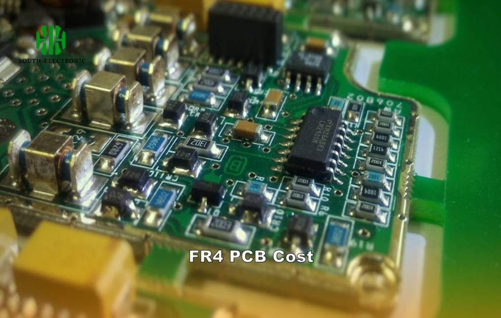
For RF projects, I once opted for Rogers 4350B over standard FR-4 despite higher costs. The substrate’s stable dielectric constant prevented performance drift, justifying the investment. Always validate material properties against operating conditions.
What Factors Significantly Impact PCB Customization Costs?
Cost overruns derail 42% of PCB projects. Hidden expenses lurk in material selections, unnecessary layers, and special processes that don’t add functional value.
Key cost drivers: layer count (+30% for 4L vs 2L), high-frequency materials[^3] (3-5x FR-4), and specialty finishes[^4] (ENIG/HASL). Optimize by reducing layers, using standard materials, and simplifying layouts.
)
Cost-Reduction Playbook
| Cost Category | Optimization Strategy | Typical Savings |
|---|---|---|
| Layer Reduction | Merge power/signal layers where possible | 15-25% |
| Material Selection | Use FR-4 unless electrical specs demand it | 20-50% |
| Panelization | Maximize boards per panel (12-15% gain) | 10-18% |
Example: A client needed 6-layer boards but reconfigured power planes, achieving the same performance with 4 layers. Savings: $820 per 100 boards. Always challenge layer requirements.
Which Specialized PCB Processes Might Extend Lead Times During Customization?
Exotic processes create bottlenecks. HDI routing adds 4-7 days, blind/buried vias require additional laser drilling steps, and impedance control needs precise material sourcing.
High-risk processes: HDI (up to 7 days extra), via-in-pad (3-5 days), RF tuning. Mitigate by pre-approving materials and confirming supplier capabilities early.
)
Lead Time Analysis
| Process | Standard Time | Extended Time | Alternatives |
|---|---|---|---|
| HDI Microvias | 14 days | 19 days | Use staggered vias |
| Gold Plating | 5 days | 7 days | Opt for ENIG finish |
| Flex-Rigid Stackup | 10 days | 16 days | Separate PCBs |
Case study: A medical device required via-in-pad, adding 4 days. Solution: Shifted components to allow through-hole vias, meeting deadline without redesign.
How to Avoid Design File Errors That Could Delay PCB Production?
A single missing drill file can cost $2,500 in respins. Common mistakes include mismatched layer counts, missing solder masks, and incorrect DRC settings.
Prevent errors with 3-step validation: Run automated DRC checks[^5], cross-verify Gerber layers in viewer tools, and confirm IPC-7351 footprints.
%[PCB Design Validation]( )
)
Error-Proofing Checklist
| Error Type | Prevention Tool | Critical Checks |
|---|---|---|
| Layer Alignment | Gerber Viewer | Drill to copper clearance |
| Annular Rings | DRC Software | Minimum 0.15mm ring width |
| Footprint Errors | IPC-7351 Library | Pad size vs component leads |
Always request a DFM report[^6] pre-production. One project had 12-mil traces but the fab house required 15-mil minimum. Catching this upfront saved 9 days.
How to Verify a Supplier’s Actual Production Capabilities and Quality Standards?
63% of PCB buyers report capability mismatches. Marketing claims often don’t match reality for laser drilled microvias, tight impedance control (±5%), or advanced surface finishes.
Validate through audit reports (IATF 16949[^7]), sample testing (TDR for impedance), and onsite visits to check 4-hour AOI/ICT processes.
)
Supplier Vetting Matrix
| Verification Method | Key Metrics | Red Flags |
|---|---|---|
| Certifications | UL, ISO 9001, IPC-A-600 Class 3 | No recent audit reports |
| Test Reports | Impedance TDR[^8] ±7% tolerance | No automated optical inspection |
| Facility Tour | SMT line calibration records | Manual soldering stations |
A client chose a "capable" supplier without checking. Their AOI couldn’t detect 0201 components, resulting in a $15k recall. Always test samples under real conditions.
Conclusion
Optimize PCB projects by aligning specs with real needs, simplifying designs for cost control, verifying DFM early, and rigorously vetting suppliers. Prototype smarter, not harder.
If you’re still searching for the perfect PCB manufacturer, look no further than South-Electronic. With years of expertise, we excel at optimizing designs for cost and performance, ensuring strict quality control, and meeting tight deadlines. Trust us to turn your PCB concepts into high – quality, reliable products. Contact us today and experience seamless customization!
[^1]: Understanding the impact of layer count on PCB design can help you make informed decisions for your projects.
[^2]: Explore this resource to learn effective strategies for optimizing your PCB customization process and avoiding common pitfalls.
[^3]: Explore the cost implications of using high-frequency materials to optimize your PCB design and budget.
[^4]: Learn about the financial impact of specialty finishes to avoid unnecessary expenses in your PCB projects.
[^5]: Understanding the role of automated DRC checks can significantly enhance your design accuracy and reduce costly errors in production.
[^6]: Learning about DFM reports will help you understand their critical role in preventing production delays and ensuring design feasibility.
[^7]: Understanding IATF 16949 can help you ensure your suppliers meet high-quality standards, reducing risks in production.
[^8]: Learning about Impedance TDR testing can enhance your knowledge of PCB quality assurance, ensuring better supplier selection.

