
RJ45 Connector Pinouts: A Complete Guide and More!
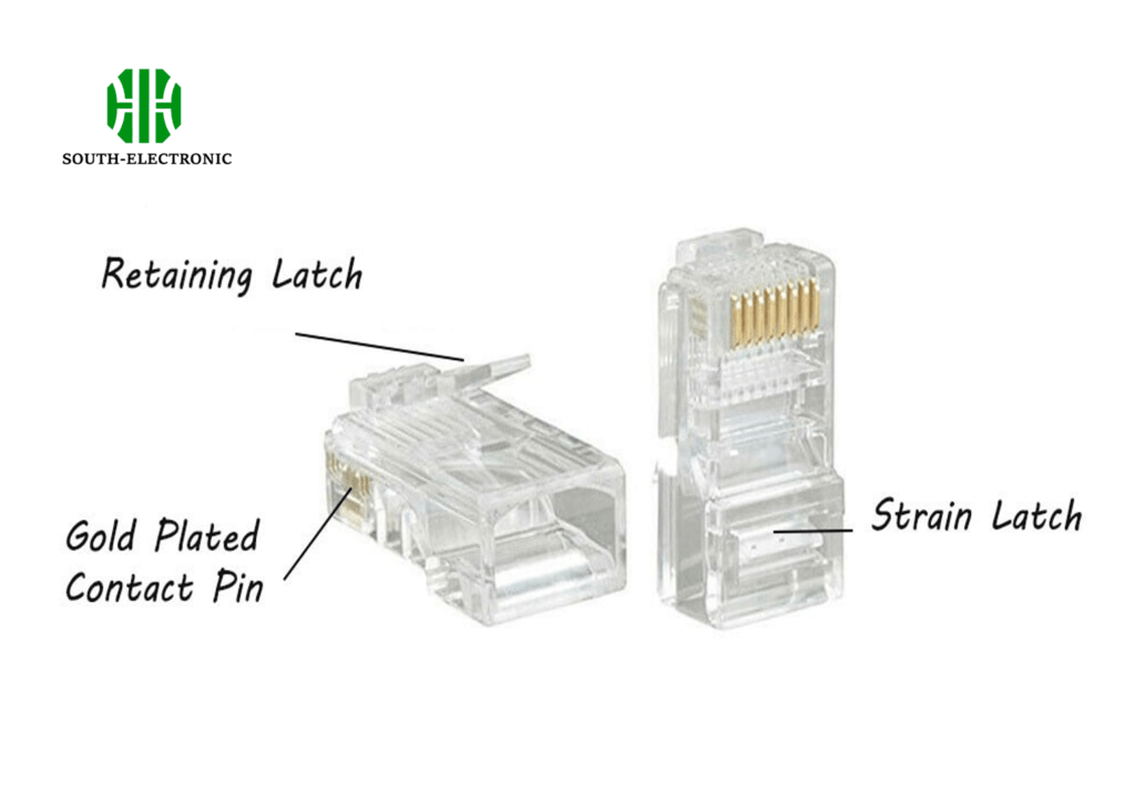
The RJ45 connector is an 8-position, 8-contact (8P8C) connector. It resembles an 8P8C connector but includes a tab to ensure proper orientation.The RJ45 pinout for straight-through Ethernet cables is: Pin 1: Transmit + (White and green), Pin 2: Transmit – (Green), Pin 3: Receive + (White and orange), Pin 4: Blue, Pin 5: White and blue, Pin 6: Receive – (Orange), Pin 7: White and brown, Pin 8: Brown.
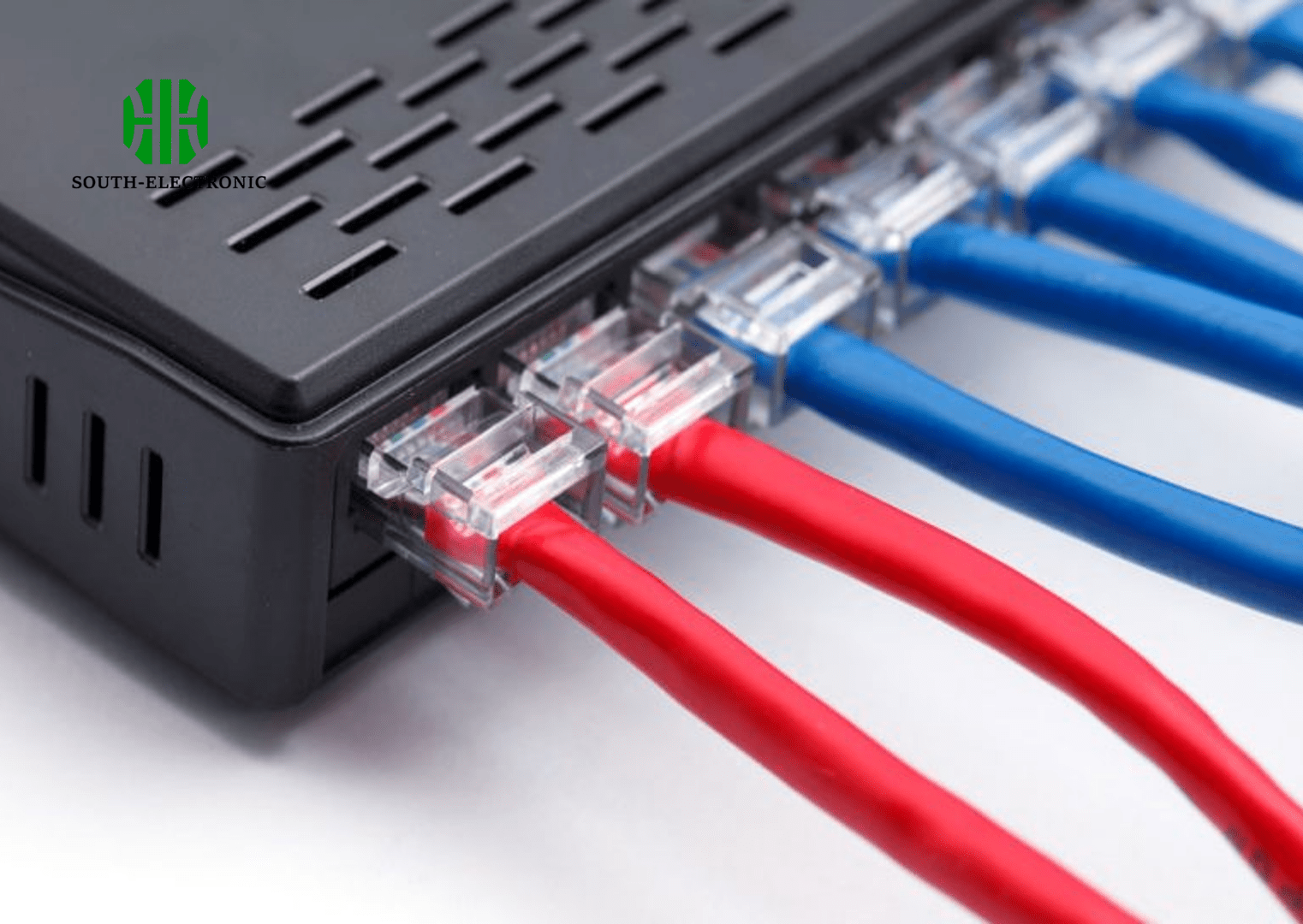
RJ45 connectors are widely used in Ethernet networking, and knowing their wiring standards can make a big difference in your projects.
What are the different RJ45 pinouts?
RJ45 connectors have several pinout configurations, each serving different purposes. The most common are:
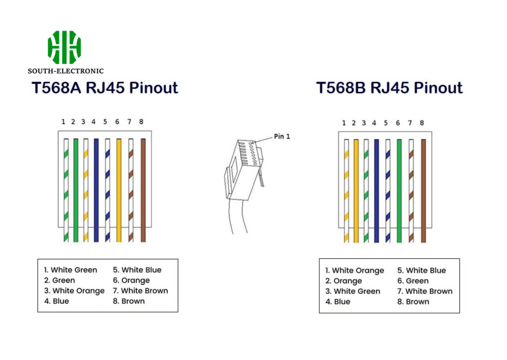
1.Straight Through Pinout (T568A or T568B)
Straight through pinouts are used for connecting devices like computers to network hubs or switches. The difference between T568A and T568B lies in the order of the colored wires.
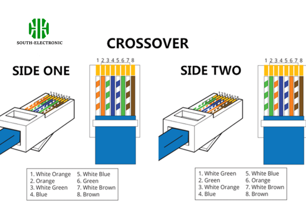
2.Crossover Pinout
Crossover cables are used for connecting two similar devices, such as two computers directly. The transmit and receive wires are crossed.
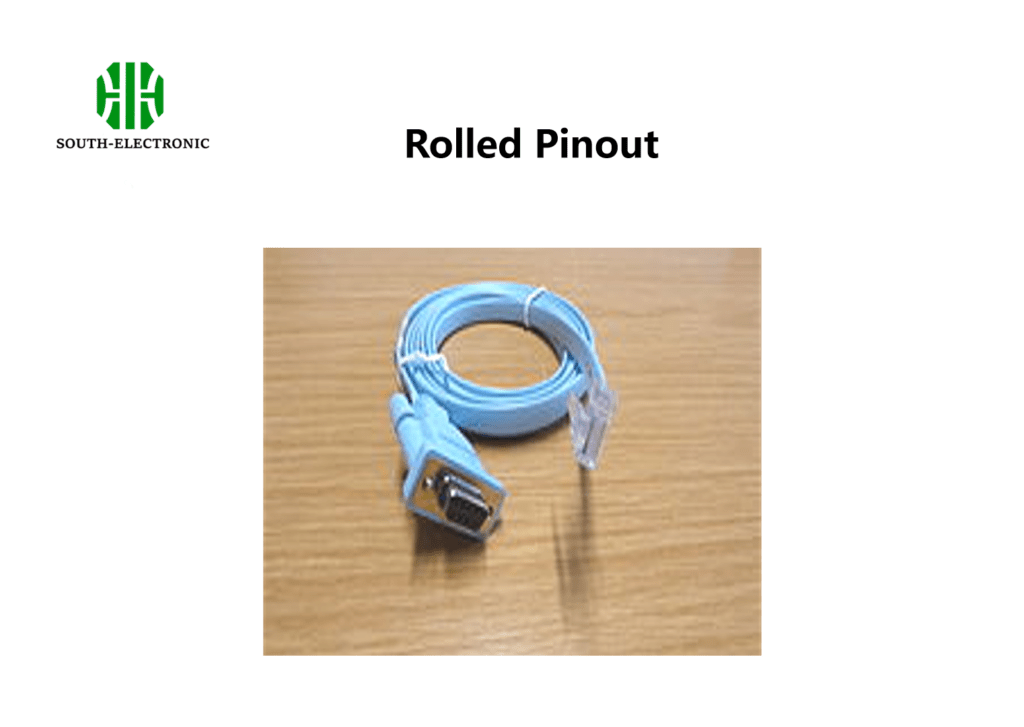
3.Rolled Pinout
Rolled pinouts are less common and typically used for serial connections.
4.T1 Pinout
T1 pinouts are used for telecommunications.
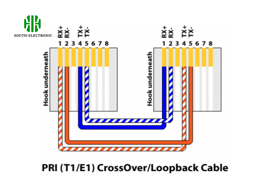
5.Loopback Pinout
Loopback pinouts are used for testing network interfaces.
What are the 8 pins of RJ45?
The 8 pins of an RJ45 connector correspond to the 8 wires in an Ethernet cable. These wires are twisted into four pairs to reduce interference.
| Pin | Color | Function |
|---|---|---|
| 1 | White/Green | Transmit + |
| 2 | Green | Transmit – |
| 3 | White/Orange | Receive + |
| 4 | Blue | Not Used |
| 5 | White/Blue | Not Used |
| 6 | Orange | Receive – |
| 7 | White/Brown | Not Used |
| 8 | Brown | Not Used |
Functions of the Pins
- Transmit + (Pin 1): Carries the positive voltage for data transmission.
- Transmit – (Pin 2): Carries the negative voltage for data transmission.
- Receive + (Pin 3): Carries the positive voltage for data reception.
- Receive – (Pin 6): Carries the negative voltage for data reception.
RJ45 connector wiring
Step-by-Step Wiring Guide:
- Strip the cable jacket.
- Untwist the wire pairs.
- Align the wires according to the T568A or T568B standard.
- Insert the wires into the connector.
- Crimp the connector.


