

Have you ever watched your high-frequency PCB design fail due to unstable signals or overheating? These nightmares vanish with Rogers PCBs – engineered laminates built for microwave frequencies and harsh environments.
A Rogers PCB uses specialized dielectric materials[^1] (like RO4000®) to provide ultra-low signal loss, stable electrical properties, and superior heat resistance, making it essential for 5G networks, aerospace systems, and radar applications where FR4 materials fall short.
Let’s dissect how Rogers PCBs[^2] dominate high-frequency designs[^3], where they’re deployed, and why they outperform standard options – knowledge critical for engineers pushing performance boundaries.
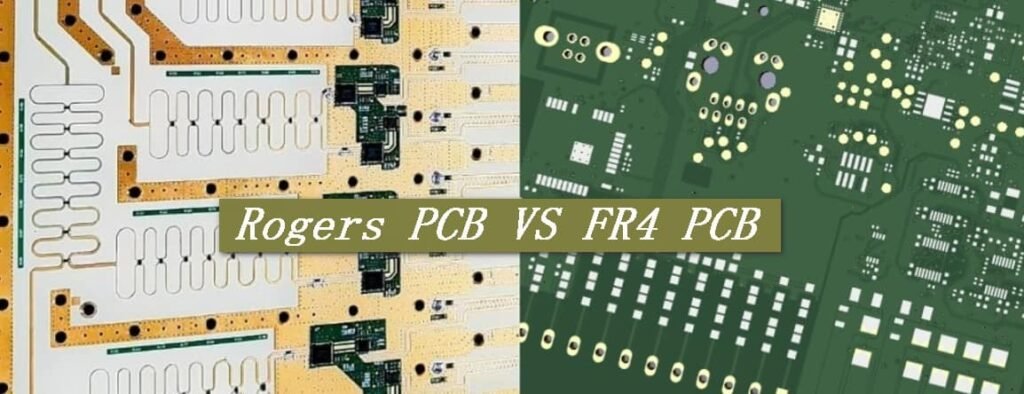
Introduction to Rogers PCB
Failed a high-frequency prototype due to erratic signal behavior? Rogers PCBs solve this by replacing traditional epoxy-glass with hydrocarbon ceramics or Teflon composites.
Rogers PCBs are circuit boards using laminates with tightly controlled dielectric constants (Dk) and dissipation factors (Df), enabling precise signal control at frequencies above 1 GHz – a realm where FR4 becomes unreliable.
)
Why Material Composition Dictates Performance
At high frequencies, every material property matters. Here’s how Rogers’ core features crush conventional boards:
| Parameter | FR4 | Rogers RO4350B |
|---|---|---|
| Dielectric Constant (Dk) | 4.5 (varies with humidity) | 3.48 ±0.05 (stable) |
| Dissipation Factor (Df) | 0.02 @ 1 GHz | 0.0037 @ 10 GHz |
| Thermal Conductivity | 0.25 W/m·K | 0.62 W/m·K |
| Moisture Absorption | >0.2% | 0.06% |
Rogers’ ceramic-filled hydrocarbon materials eliminate FR4’s Achilles’ heel: Dk variance[^4]. Humidity won’t detune your filters, and extreme temperatures won’t warp impedance. A 28 GHz 5G antenna designed on RO4835™ shows 40% lower insertion loss than FR4 equivalents.
Where Are Rogers PCBs Commonly Used?
Ever wondered why satellite signals penetrate storms yet your WiFi drops when it rains? Aerospace-grade Rogers PCBs handle what consumer electronics can’t.
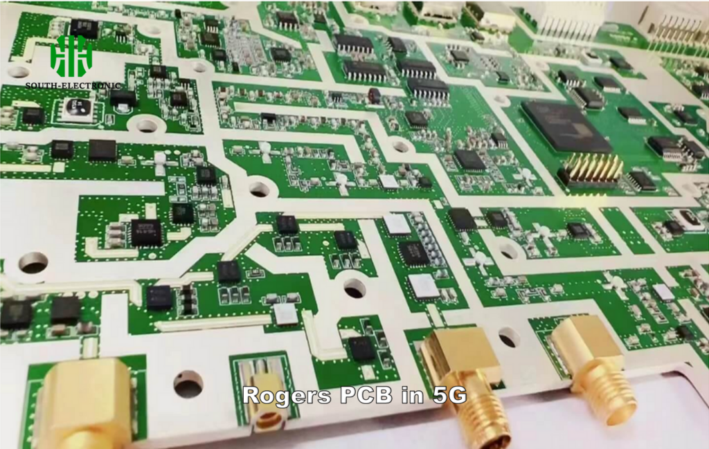
Rogers PCBs dominate applications requiring millimeter-wave stability[^5]: 5G base stations (24-39 GHz), radar altimeters, satellite uplinks, and automotive collision-avoidance systems[^6] operating in -55°C to 288°C ranges.
)
Mission-Critical Sectors Relying on Rogers
Applications split based on frequency and environmental needs:
| Industry | Frequency Range | Key Rogers Material | Why It’s Used |
|---|---|---|---|
| Aerospace Radar | 10-40 GHz | RT/duroid® 5880 | Stable Dk at cryogenic temps |
| 5G mMIMO Antennas | 24-47 GHz | RO4835™ | Low loss tangent @ mmWave |
| Automotive Radar | 76-81 GHz | RO3003™ | Crash-resistant Z-axis expansion |
| Biomedical Imaging | 3-30 GHz | RO3203™ | Consistent Dk for MRI accuracy |
I once saw a drone’s FR4-based radar fail at 5,000 ft due to signal drift. Switching to RT/duroid® 6002 cut latency by 22% – critical for real-time terrain mapping.
Why Choose Rogers Over FR4?
FR4 costs less upfront – until your 5G antenna array[^7] needs post-production tuning. Rogers prevents hidden costs of instability.
Choose Rogers PCBs when your design operates above 2 GHz, requires tight impedance control (±1% vs FR4’s ±15%), or faces thermal cycling. It reduces signal loss[^8] by 60-80% in mmWave designs.
Cost-Benefit Breakdown: Beyond the Price Tag
Short-term savings vs long-term reliability:
| Factor | FR4 | Rogers | Impact |
|---|---|---|---|
| Initial Cost | $5/sq ft | $30-$100/sq ft | ROI in high-volume RF projects |
| Signal Loss @ 10 GHz | 0.8 dB/inch | 0.2 dB/inch | Longer trace runs possible |
| Thermal Expansion | 14 ppm/°C | 8 ppm/°C (X-Y axes) | Stable plated holes in thermal cycles |
| Rework Cycles | 2-3 cycles before delam | 5+ cycles | Lower prototyping waste |
Even counting the higher material cost, a 77 GHz automotive radar using RO3003™ lasts 8 years vs FR4’s 3-year lifespan in thermal shock tests.
Understanding Rogers Materials: Dk, Df, and Thermal Stability Explained
Random Dk fluctuations ruin phased-array calibration. Rogers’ ±0.04 Dk tolerance across 40 GHz keeps beamforming precise.
Dk (dielectric constant) defines signal speed, Df (loss tangent) determines energy loss as heat, and thermal stability ensures consistent performance from -150°C (space) to +200°C (engine bays).
Balancing Material Properties for Your Design
| Material Series | Dk @ 10 GHz | Df @ 10 GHz | Max Operating Temp | Best For |
|---|---|---|---|---|
| RT/duroid® 5880 | 2.20 | 0.0009 | 150°C | UAV satellite comms |
| RO4000® | 3.38-6.15 | 0.0027 | 280°C | Automotive radar |
| TMM® 10 | 9.80 | 0.0020 | 125°C | High-Dk filters |
| RO3000® | 3.00 | 0.0013 | 260°C | 5G antenna substrates |
While RO4350B’s Dk of 3.48 is popular, a defense client needed Dk=6.15 (RO4360™) to shrink a missile’s seeker head PCB by 37% without sacrificing gain.
Conclusion
Rogers PCBs deliver unmatched high-frequency stability for 5G, radar, and aerospace – where minor signal errors cause system failures. Choose them when FR4’s limitations risk your design’s reliability.
[^1]: Learn about the role of dielectric materials in PCB design to enhance signal integrity and thermal management.
[^2]: Explore the benefits of Rogers PCBs to understand why they are essential for high-frequency applications and outperform traditional options.
[^3]: Discover the unique challenges of high-frequency PCB designs and how to overcome them for better performance.
[^4]: Understanding Dk variance is crucial for selecting the right PCB material for high-frequency applications. Explore this link for detailed insights.
[^5]: Millimeter-wave stability is essential for reliable performance in advanced communication systems. Discover more about its significance here.
[^6]: Learn how these systems enhance vehicle safety and the role of advanced PCBs in their functionality. This resource provides valuable information.
[^7]: Explore how Rogers materials enhance performance and reliability in 5G antenna arrays, ensuring optimal signal quality.
[^8]: Understanding signal loss differences can help you make informed decisions for high-frequency applications.

