Услуги по проектированию HDI PCB
South-Electronic
В South-Electronic у нас есть передовые технологии высокой плотности соединений (HDI), чтобы гарантировать, что каждый проект PCB выполняется максимально точно и эффективно. Если вы хотите, чтобы ваша PCB была надежной и хорошо функционировала, наши HDI PCB — это то, что вам нужно.
Почему выбирают South-Electronic?
-
Индивидуальный дизайн
Индивидуальный дизайн для удовлетворения ваших уникальных потребностей. В South-Electronic мы понимаем, что каждый проект уникален. Поэтому наши услуги по проектированию PCB адаптированы под ваши конкретные требования, гарантируя выполнение каждого элемента в точном соответствии с вашими спецификациями. Это улучшит производительность и надежность ваших продуктов.
-
Гарантированное удовлетворение
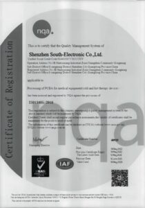
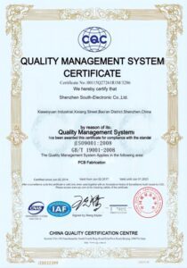
Вы оцените уверенность, которую дает работа с сертифицированной компанией ISO9001. Мы уделяем приоритетное внимание прозрачному и четкому общению и придерживаемся самых высоких стандартов, чтобы ваши PCB не только соответствовали, но и превосходили ваши ожидания по производительности, долговечности и точности.
-
Полный комплекс услуг
Вы получаете полное решение для PCB, от проектирования и прототипирования до массового производства. Мы предлагаем полный спектр услуг, устраняя сложность и затраты, связанные с работой с несколькими поставщиками.
-
Комплексный сервис
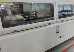
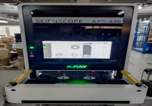
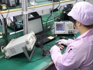
Вы получите полное удовлетворение благодаря нашему широкому спектру оборудования. У нас есть широкий спектр возможностей обработки PCB. От проектирования до доставки у нас есть оборудование и процессы, чтобы обеспечить правильное выполнение вашего заказа.
-
Быстрая доставка
Оставайтесь в рамках графика благодаря нашим быстрым срокам выполнения. Наш оптимизированный производственный процесс гарантирует быстрые сроки выполнения заказов, чтобы вы получали свою продукцию вовремя, без задержек.
Связанные проекты, которые мы выполнили
Отзывы клиентов
Часто задаваемые вопросы
Самые популярные вопросы
Отправьте нам сообщение
Чем подробнее вы заполните, тем быстрее мы сможем перейти к следующему шагу.








Полное руководство по проектированию HDI PCB
Содержание
Глава 1
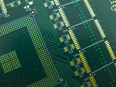
Введение в проектирование HDI PCB
Обзор технологии HDI в PCB
Технология высокой плотности соединений (HDI) совершила прорыв в мире проектирования печатных плат (PCB). Она позволяет размещать больше компонентов на меньшем пространстве, чем когда-либо прежде. Как? Используя более тонкие линии, меньшие виа и размещая компоненты ближе друг к другу. Понимание технологии HDI поможет вам проектировать более компактные, эффективные и высокопроизводительные устройства, погружаясь в мир электроники. HDI PCB используют передовые методы, такие как микровиа, многослойные платы с последовательным наращиванием и обеспечение целостности сигнала на высоких частотах, чтобы расширить возможности ваших продуктов за пределы традиционных дизайнов.
Значение и эволюция HDI PCB в современной электронике
HDI PCB играют важную роль в современной электронной промышленности. По мере того как устройства становятся меньше и сложнее, растет потребность в платах, которые могут поддерживать высокую плотность компонентов без потери производительности. Технология HDI удовлетворяет эту потребность. Она прошла путь от способа улучшения внешнего вида и работы потребительской электроники до ключевого элемента в критически важных приложениях, таких как медицинские устройства, автомобильные системы и аэрокосмическая техника. Это возможно благодаря постоянному развитию методов производства и материаловедения, что позволяет вам расширять границы возможного в электронных разработках.
Ключевые термины и определения
Знание этих ключевых терминов поможет вам быстрее понять и освоить область HDI PCB:
- Микровиа: Небольшие отверстия, просверленные лазером для соединения различных слоев PCB. Они важны, так как экономят пространство и улучшают производительность HDI плат.
- Многослойные платы с последовательным наращиванием: Метод, при котором дополнительные слои последовательно добавляются к базовым медным слоям, что позволяет создавать более компактные конструкции плат.
- Целостность сигнала: Показатель качества электрического сигнала, который имеет первостепенное значение в HDI PCB для обеспечения функциональности и производительности.
- Плотность контактных площадок: Относится к количеству контактных площадок на единицу площади платы, которое обычно выше у HDI PCB по сравнению с обычными.
Глава 2
Преимущества HDI PCB
Повышенная электрическая производительность
Выбирая HDI PCB, вы делаете ставку на превосходную электрическую производительность, которая крайне важна для современной высокоскоростной электроники. Использование микровиа и плотных соединений в HDI платах приводит к сокращению электрических путей, снижению перекрестных помех и улучшению целостности сигнала. Это означает более высокие скорости передачи сигналов и надежность работы ваших электронных устройств. Независимо от того, разрабатываете ли вы устройства для потребительской электроники, телекоммуникаций или высокочастотных приложений, HDI PCB предоставляют те улучшения производительности, которые помогут вам оставаться конкурентоспособными.
Увеличение плотности схем и ее преимущества
Отличительная черта технологии HDI — это способность увеличивать плотность схем. Это означает больше функциональности на меньшем пространстве, что критически важно, так как электронные устройства продолжают уменьшаться в размерах, становясь при этом все сложнее. Для вас это означает возможность проектировать более компактные устройства без потери производительности: смартфоны, умные часы и медицинские имплантаты. Увеличение плотности схем также способствует лучшему управлению теплом и повышению энергоэффективности, что важно для долговечности и устойчивости ваших продуктов.
Надежность и долговечность в сложных условиях
Выбирая HDI PCB, вы инвестируете в надежность и долговечность, особенно важные в сложных условиях, таких как автомобильная промышленность, аэрокосмическая техника и промышленная электроника. HDI платы отличаются прочностью благодаря использованию передовых материалов и инновационным методам наращивания слоев, что позволяет им выдерживать экстремальные условия, такие как высокие температуры, вибрации и влажность. Эта долговечность не только увеличивает срок службы электронных компонентов, но и обеспечивает стабильную работу под нагрузкой, что дает вам уверенность в том, что ваш продукт будет работать так, как ожидается, независимо от условий.
В итоге HDI PCB предлагают вам тройное преимущество: непревзойденную электрическую производительность, увеличенную плотность схем для миниатюризации и исключительную надежность и долговечность. Эти преимущества незаменимы в условиях быстро меняющегося технологического ландшафта, где требования к электронным устройствам становятся все выше. Интегрируя HDI PCB в свои разработки, вы не только соответствуете стандартам отрасли, но и устанавливаете их.
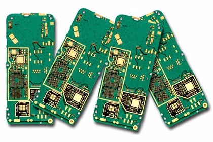
Глава 3
Особенности проектирования HDI PCB
Выбор материалов для HDI PCB
Материалы, которые вы выбираете, напрямую влияют на производительность и надежность ваших электронных устройств. Необходимо выбирать подложки, которые поддерживают точное травление линий и обеспечивают отличную термостабильность и низкие диэлектрические потери, особенно для высокочастотных приложений. Высокопроизводительные материалы, такие как FR-4 с высоким TG, полиимид и BT-смола, являются популярным выбором, отвечающим этим требованиям. Каждый материал имеет свои преимущества, такие как улучшенная термостойкость или улучшенные механические свойства, что позволяет адаптировать PCB к специфическим требованиям вашего проекта. Правильный выбор материалов гарантирует, что ваши HDI PCB смогут поддерживать плотные схемы компонентов и быть достаточно долговечными для эксплуатации в сложных условиях.
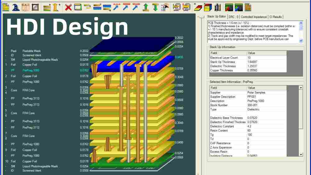
Конфигурация слоев и особенности стековки
Конфигурация слоев и стековка имеют решающее значение для максимального использования преимуществ HDI технологий. При проектировании HDI PCB важно учитывать, как расположение слоев влияет на электрическую производительность и технологичность платы. Правильная конфигурация слоев помогает уменьшить проблемы с целостностью сигнала, минимизируя расстояния, которые должны преодолевать сигналы между компонентами, сокращая задержки и помехи. Хорошо продуманная стековка также улучшает тепловое управление платой, что особенно важно для схем с высокой плотностью. Распространенные конфигурации включают использование закопанных и сквозных виа, что освобождает поверхность для дополнительных компонентов. Такая стратегическая слоистая структура не только оптимизирует электрические характеристики, но и способствует миниатюризации устройства, позволяя расширять возможности ваших продуктов.
Типы виа, используемые в HDI PCB
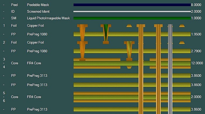
Виа являются основным элементом HDI PCB и играют ключевую роль в межслойных соединениях. Понимание доступных типов виа и их эффективное использование являются важными аспектами проектирования. Микровиа, представляющие собой отверстия малого диаметра, сверленные лазером, являются характерной чертой HDI дизайна. Они обеспечивают высокую плотность трассировки, но могут использоваться только для нескольких слоев. Закопанные виа, скрытые внутри платы, и слепые виа, соединяющие внешние слои с одним или несколькими внутренними, помогают создавать более компактные и эффективные конструкции. Эффективное использование различных типов виа значительно улучшает производительность HDI PCB, минимизируя длину пути для электрических сигналов и оптимизируя использование пространства на каждом слое.
Тщательно учитывая выбор материалов, конфигурацию слоев и типы виа, вы создаете передовые HDI PCB, обеспечивающие надежность и эффективность, необходимые для удовлетворения современных технологических требований. Сосредоточившись на этих ключевых аспектах, вы обеспечиваете превосходство ваших электронных продуктов как в производительности, так и в надежности.
Глава 4
Процесс проектирования HDI PCB
Пошаговое руководство от концепции до финального дизайна
Проектирование HDI PCB начинается с вашей идеи. Необходимо представить, что вы хотите от своего электронного устройства и какие задачи оно должно решать. Вот пошаговый процесс разработки:
- Анализ требований: Начните с определения требований к производительности, ограничений по размеру и условий эксплуатации, которые должна выдерживать ваша плата. Эти аспекты определяют сложность разработки и производства.
- Создание схемы: Затем создайте подробную схему, отображающую все электрические соединения между компонентами. Это важный этап, на котором вы проектируете цепь и определяете размещение компонентов, что существенно влияет на производительность и технологичность HDI PCB.
- Создание макета платы: На основе схемы переходите к разработке макета платы. На этом этапе осуществляется размещение компонентов и трассировка цепей в соответствии с рекомендациями HDI для оптимизации пространства и улучшения целостности сигнала.
- Планирование стека слоев: Определите количество слоев и их расположение в зависимости от сложности схемы и требований к распределению мощности. Это включает выбор подходящих типов виа (микровиа, закопанные виа) для эффективного соединения слоев.
- Симуляция и тестирование: Перед финализацией дизайна выполните симуляции для проверки электрических характеристик, включая целостность сигнала и тепловые параметры. Устраните выявленные проблемы, чтобы избежать дорогостоящих изменений в будущем.
- Изготовление прототипа: После завершения проектирования изготовьте прототип для физического тестирования конструкции. Этот этап часто требует корректировок на основе результатов тестирования.
- Финальная итерация и производство: После тщательного тестирования и доработок финализируйте проект для серийного производства. Убедитесь, что все спецификации соблюдены для обеспечения оптимальной производительности в предполагаемых приложениях.
Рекомендуемые инструменты и ПО для проектирования HDI PCB
Эффективное проектирование HDI PCB требует современных инструментов, способных справляться со сложностями плотных схем:
- САПР: Используйте такие передовые САПР, как Altium Designer, Cadence Allegro или Mentor Graphics PADS, для точного проектирования. Эти инструменты обеспечивают мощные функции управления слоями, авторазводки и 3D-визуализации стека.
- Инструменты для симуляции: Программы, такие как ANSYS или HyperLynx, незаменимы для анализа целостности сигнала и тепловых характеристик, что помогает выявить и устранить проблемы до создания физических прототипов.
Советы по эффективному созданию схемы и планированию макета
- Размещайте компоненты рядом: Размещайте связанные компоненты близко друг к другу, чтобы минимизировать длину трасс, снижая деградацию сигнала и помехи.
- Используйте HDI технологии: Максимально используйте микровиа и технологии via-in-pad для увеличения пространства и улучшения производительности.
- Учитывайте тепловые потоки: Продумайте тепловые пути в конструкции, чтобы эффективно управлять температурой, особенно в плотных платах.
- Проводите регулярные тесты: Интегрируйте тестирование на всех этапах проектирования. Раннее обнаружение проблем позволяет существенно сэкономить время и ресурсы.
Следуя этим шагам и используя правильные инструменты, вы сможете эффективно справляться со сложностями проектирования HDI PCB, обеспечивая, чтобы конечный продукт не только соответствовал, но и превосходил ожидания. Этот процесс требует не только технических знаний, но и дальновидного подхода к интеграции формы, функции и готовности к будущим технологиям.
Глава 5
Техники производства HDI PCB
Обзор уникальных процессов производства HDI PCB
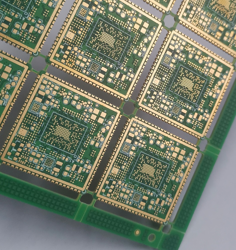
Производство печатных плат высокой плотности (HDI) включает сложные технологии, разработанные для удовлетворения особых требований к повышенной плотности компонентов и более тонким линиям. При работе с этими передовыми платами вы столкнетесь с процессами, такими как формирование микровиа, последовательная ламинация и прямая лазерная сверловка, которые необходимы для достижения компактных и эффективных конструкций, характерных для HDI технологий. Эти процессы позволяют уменьшить количество слоев, одновременно увеличивая функциональность, что крайне важно для современных электронных устройств, требующих минимального размера без потери производительности.
Основные производственные проблемы и их решения
Производство HDI PCB сопряжено с рядом сложностей, но при правильных подходах их можно эффективно преодолеть:
- Формирование микровиа: Одной из самых сложных задач является создание микровиа — небольших отверстий, сверленных в PCB для соединения различных слоев. Это требует точного контроля, чтобы избежать таких дефектов, как неполное сверление или пустоты в металлизации. Использование современного лазерного оборудования обеспечивает точность и консистентность при формировании микровиа.
- Выравнивание слоев: С увеличением количества слоев поддержание идеального выравнивания становится критически важным и сложным. Неправильное выравнивание может привести к сбоям соединений и снижению надежности. Применение оптических методов инспекции в процессе ламинации помогает гарантировать точное выравнивание каждого слоя.
- Целостность сигнала: Сохранение целостности сигнала в платах с высокой плотностью компонентов является ключевым моментом. Использование симуляционных инструментов на этапе проектирования позволяет предсказать потенциальные проблемы взаимодействия сигналов. Дополнительно, тщательное планирование трассировки и применение методов экранирования во время производства помогут минимизировать эти эффекты.
Оборудование и технологии, используемые в производстве
Для удовлетворения требований производства HDI PCB ваше предприятие должно быть оснащено современным оборудованием:
- Лазерные сверлильные машины: Необходимы для создания микровиа, такие машины обеспечивают высокую точность и контроль, что делает их идеальными для небольших размеров, требуемых в HDI PCB.
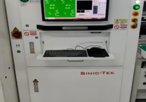
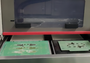
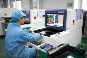
- Системы автоматической оптической инспекции (AOI): Эти системы крайне важны для проверки каждого слоя PCB на отсутствие дефектов и правильное выравнивание перед переходом к следующему этапу производства.
- Оборудование для гальваники: Правильная металлизация виа и дорожек критически важна для функциональности HDI PCB. Современные системы гальваники обеспечивают необходимый контроль для получения стабильной и надежной металлизации, особенно в случае микровиа и тонких дорожек.
- Прессы для последовательной ламинации: Используются для склеивания множества слоев HDI PCB при контролируемых температуре и давлении, обеспечивая прочное соединение и точное совмещение слоев.
Освоив эти техники и используя соответствующее оборудование, вы сможете производить HDI PCB высокого качества, отвечающие строгим требованиям передовых электронных приложений. Это не только повысит надежность и производительность создаваемой вами продукции, но и выведет ваше производство на лидирующие позиции в электронной промышленности.
Глава 6
Тестирование и обеспечение качества HDI PCB
Основные методы тестирования
Для обеспечения надежной работы HDI PCB в любых условиях необходимо внедрить комплексный набор тестов. Вот основные методы тестирования, которые следует использовать:
- Электрическое тестирование: Проверка на наличие коротких замыканий, разрывов цепей и корректных значений импеданса для обеспечения электрической функциональности. С помощью тестеров с летающим зондом или контактных тестеров («постель из гвоздей») можно быстро и эффективно проводить эти тесты без прямого контакта с каждым компонентом цепи, что идеально подходит для плотных макетов HDI PCB.
- Тепловое тестирование: Учитывая компактный характер HDI PCB, управление теплом является критически важным. Тепловое тестирование проверяет, могут ли платы эффективно работать при различных температурных условиях без снижения производительности. Часто используется метод циклического температурного тестирования, при котором PCB подвергается воздействию переменных температур для имитации рабочих условий.
- Тестирование целостности сигнала: С ростом частот задача сохранения целостности сигнала становится более сложной. Тесты на целостность сигнала гарантируют, что PCB передает сигналы без искажений или потерь, что особенно важно для высокоскоростных приложений.
Стандарты качества, применимые к HDI PCB
Соответствие признанным стандартам качества не только обеспечивает соответствие требованиям, но и гарантирует долговечность и надежность HDI PCB. Вот некоторые из них:
- IPC-6012: Этот стандарт регулирует квалификацию и спецификации производительности для жестких печатных плат, включая HDI конструкции. Соответствие IPC-6012 обеспечивает соответствие строгим требованиям надежности и качества.
- ISO 9001: Хотя этот стандарт не специфичен для PCB, сертификация ISO 9001 в производственных процессах гарантирует наличие надежной системы управления качеством, что повышает стабильность и удовлетворенность клиентов.
- IPC-A-600: Известный как «Приемлемость печатных плат,» этот стандарт помогает визуально оценивать качество PCB, уделяя внимание таким критериям, как качество материалов, состояние поверхности и качество отверстий, что особенно важно для HDI PCB.
Обращение и проверка в процессе QA
Обращение и проверка являются важными этапами процесса обеспечения качества, особенно для HDI PCB, где даже небольшие дефекты могут привести к значительным проблемам:
- Автоматическая оптическая инспекция (AOI): До и после сборки используйте системы AOI для проверки поверхностных дефектов, таких как царапины или ошибки травления. Этот метод особенно эффективен на ранних этапах, чтобы предотвратить дальнейшую обработку дефектных плат.
- Рентгеновская инспекция: Критически важна для проверки микровиа и других скрытых элементов, невидимых невооруженным глазом. Рентгеновская инспекция позволяет проверить целостность внутренних слоев и соединений, гарантируя отсутствие дефектов, таких как пустоты или смещения.
- Ручная проверка: Хотя автоматизированные методы эффективны, ручная проверка опытным персоналом может быть незаменимой, особенно на финальных этапах. Это позволяет выявить проблемы, которые могли быть пропущены машинами, и добавляет дополнительный уровень гарантии перед отправкой продукции.
Реализуя эти методы тестирования и следуя строгим стандартам качества, вы предоставляете клиентам HDI PCB, которые не только соответствуют, но и превосходят ожидания по производительности и надежности. Такой подход к обеспечению качества выделяет вас на фоне конкурентов в сфере производства электроники.
Глава 7

Применение HDI PCB
Примеры использования в различных отраслях
HDI PCB являются неотъемлемой частью многих отраслей, каждая из которых получает выгоду от уникальных возможностей этих решений с высокой плотностью соединений:
- Автомобилестроение: В автомобильной отрасли HDI PCB играют ключевую роль в поддержке сложной электроники современных автомобилей. От информационно-развлекательных систем до систем безопасности, таких как контроллеры подушек безопасности и антиблокировочные системы тормозов, HDI PCB обеспечивают необходимую надежность и производительность в условиях вибрации и экстремальных температур.
- Аэрокосмическая отрасль: Аэрокосмические приложения требуют максимальной надежности и точности, и HDI PCB это обеспечивают. Они используются в приборных панелях, системах связи и спутниковой навигации, где их способность обрабатывать высокочастотные сигналы незаменима.
- Потребительская электроника: В потребительской электронике HDI PCB позволяют уменьшать размеры устройств, таких как смартфоны, планшеты и носимые гаджеты. Они обеспечивают размещение большего количества функций в компактных пространствах без ущерба для производительности, создавая более стильные и мощные устройства.
- Медицинские устройства: HDI PCB широко используются в медицинском оборудовании, включая системы визуализации и портативные диагностические инструменты. Их высокая надежность и компактный размер делают их идеальными для критически важных медицинских приложений, где важны точность и долговечность.
Примеры из практики, демонстрирующие влияние HDI PCB
- Инновации в смартфонах: Один из ведущих производителей смартфонов использовал HDI PCB, чтобы революционизировать свою последнюю модель. Благодаря интеграции HDI технологии удалось вдвое увеличить время работы батареи и улучшить функциональность камеры, не увеличивая размеры телефона, предложив потребителям более мощное устройство.
- Улучшение автомобильной безопасности: Автокомпания внедрила HDI PCB в свои системы безопасности, значительно повысив отзывчивость и надежность функций аварийного реагирования своих автомобилей. Эта инновация позволила компании получить более высокие рейтинги безопасности, что укрепило доверие клиентов и увеличило продажи.
Будущие тенденции в применении
Будущее HDI PCB обещает еще более широкие области применения и инновации:
- Интернет вещей (IoT): С распространением IoT-устройств растет спрос на компактные и высокопроизводительные PCB. HDI PCB идеально подходят для этих целей, обеспечивая возможность подключения множества датчиков и актуаторов в ограниченном пространстве.
- Носимая электроника: Индустрия носимой электроники быстро развивается, и HDI PCB находятся в ее центре. Их способность вписываться в небольшие и иногда нестандартные пространства, сохраняя функциональность, делает их идеальными для этой области.
- Искусственный интеллект (AI): С развитием AI электроника, поддерживающая его, должна обрабатывать все больше данных на высоких скоростях. HDI PCB с их превосходной целостностью сигнала и высокой плотностью являются ключевым элементом для того, чтобы сделать AI более доступным в повседневных устройствах.
Интегрируя HDI PCB в свою продукцию, вы не только соответствуете текущим технологическим тенденциям, но и опережаете их, готовясь к вызовам завтрашнего дня. Такой подход к инновациям обеспечивает, что ваши разработки будут продолжать расширять границы возможного, оказывая значительное влияние на различные отрасли.
Глава 8
Проблемы и решения в проектировании HDI PCB
Решение проблем с целостностью сигнала
Целостность сигнала — это ключевая задача в проектировании HDI PCB из-за высокой плотности и компактности плат. При работе с высокоскоростными сигналами могут возникнуть проблемы, такие как перекрестные помехи, несоответствие импеданса и отражения сигнала, которые снижают производительность электроники.
Решения:
- Аккуратная трассировка и экранирование: Используйте дифференциальную сигнализацию, где это возможно, и применяйте слои земли для экранирования высокоскоростных трасс. Это снижает перекрестные помехи и электромагнитные интерференции, сохраняя целостность сигналов.
- Контроль импеданса: Обеспечьте постоянный импеданс на всей плате с помощью линий с контролируемым импедансом. Это требует точных расчетов и корректировок на этапе проектирования, чтобы импеданс соответствовал требованиям компонентов и сигналов.
- Использование современных материалов: Рассмотрите возможность применения материалов с низкими диэлектрическими постоянными и потерями, что помогает сохранить целостность сигналов на высоких частотах.
Управление теплом в плотных макетах
С увеличением плотности компонентов растет и тепловая нагрузка. HDI PCB часто содержат больше активных компонентов на меньшей площади, что может привести к значительному нагреву, влияющему на надежность и срок службы компонентов.
Решения:
- Размещение тепловых виа: Добавляйте тепловые виа возле компонентов, генерирующих тепло, для более эффективного рассеивания тепла. Эти виа работают как тепловые каналы, отводя тепло к радиаторам или внешним слоям платы.
- Выбор материалов: Используйте подложки с высокой теплопроводностью. Материалы, такие как платы с алюминиевой или медной основой, лучше справляются с теплом, чем стандартные материалы.
- Эффективная компоновка компонентов: Стратегически размещайте компоненты, чтобы равномерно распределять тепло по плате. Избегайте скопления тепловосприимчивых компонентов, если это не абсолютно необходимо.
Преодоление сложности дизайна с инновационными решениями
Сложная природа HDI PCB влечет за собой множество задач, включая обеспечение необходимой связи и поддержание технологичности без ущерба для производительности.
Решения:
- Современное программное обеспечение для проектирования: Используйте передовые САПР для проектирования PCB с функциями авторазводки, калькуляторов импеданса и инструментов теплового анализа. Эти решения позволяют визуализировать и оптимизировать макеты до производства прототипов.
- Прототипирование и итерации: Занимайтесь быстрым прототипированием для тестирования и доработки ваших проектов PCB. Это позволяет выявлять и устранять проблемы на ранних этапах проектирования, экономя время и сокращая затраты в долгосрочной перспективе.
- Коллаборативный подход к проектированию: Тесно сотрудничайте с производственными партнерами с самого начала. Их опыт поможет адаптировать ваши проекты к производственным возможностям, обеспечивая более плавный переход от проектирования к производству.
Решая эти задачи с помощью целевых решений, вы усиливаете свои HDI PCB, чтобы они соответствовали высоким требованиям современной электроники, гарантируя надежность и эффективность ваших продуктов. Такой подход к решению проблем в проектировании HDI PCB не только улучшает качество конечной продукции, но и укрепляет ваше лидерство в области разработки передовой электроники.
Глава 9

Учёт и оптимизация затрат
Анализ факторов стоимости при производстве HDI PCB
Понимание факторов стоимости при производстве HDI PCB является ключом к управлению бюджетом и ожиданиями. При планировании проекта HDI PCB несколько факторов могут значительно увеличить расходы:
- Стоимость материалов: HDI PCB часто требуют специализированных материалов, способных работать с более высокими частотами и плотностями, таких как продвинутые смолы и медные фольги, которые дороже стандартных материалов.
- Сложные производственные процессы: Технологии, такие как лазерное сверление, последовательная ламинация и травление тонких линий, являются неотъемлемой частью HDI PCB, но они сложны и трудоемки, что увеличивает производственные затраты.
- Сложность дизайна: Более сложные проекты с большим количеством слоев, микровиа и компактными макетами требуют более точной и трудоемкой работы, что увеличивает общую стоимость.
Стратегии для экономичного проектирования и производства HDI PCB
Чтобы управлять затратами и оптимизировать их без ущерба для качества, рассмотрите следующие стратегии:
- Эффективные методы проектирования: Минимизируйте использование лишних слоев и микровиа. Планируйте макет так, чтобы использовать минимально сложную структуру при соблюдении требований к производительности. Инструменты, такие как проверка проектируемости (DFM), помогут выявить возможности для экономии.
- Выбор материалов: Оценивайте соотношение цены и производительности различных материалов. Иногда более дешевые материалы могут соответствовать требованиям, особенно если устройство не подвергается экстремальным условиям.
- Учет объёмов: Большие объемы производства могут снизить стоимость на единицу. Если предполагается регулярная потребность, серийное производство может обеспечить значительную экономию. Заключение долгосрочных контрактов с поставщиками также может привести к улучшению условий и снижению цен.
Балансировка производительности и стоимости
Сочетание высокой производительности HDI PCB с бюджетными ограничениями — это важная задача. Вот как можно эффективно достичь этого баланса:
- Определение ключевых функций: Выявите, какие функции вашей PCB критически важны для производительности, а какие можно скорректировать или исключить без значительного ущерба. Сосредоточьте бюджет на приоритетных областях, которые непосредственно влияют на функциональность продукта.
- Итерационные тесты и проверки: Внедрите строгую систему тестирования на ранних этапах проектирования. Раннее выявление и исправление ошибок позволяет избежать дорогостоящих доработок в будущем.
- Сотрудничество с производителями: Тесно работайте с производителями PCB, чтобы понимать их возможности и ограничения. Они могут предложить альтернативные технологии или материалы, которые позволят снизить затраты, сохраняя желаемые характеристики.
Применяя эти стратегии, вы сможете эффективно управлять затратами на производство HDI PCB, обеспечивая соответствие продукции высоким стандартам производительности. Это позволит вашим проектам оставаться финансово жизнеспособными и конкурентоспособными на рынке, предлагая клиентам решения высокого качества и по приемлемой цене.
Глава 10
Будущее технологий HDI PCB
Новые тенденции и технологии в проектировании HDI PCB
Смотрясь в будущее, технология HDI PCB готова развиваться за счет интеграции все более сложных технологий, которые расширяют возможности и функциональность дизайна:
- 3D PCB: Появляющиеся технологии 3D-печати начинают применяться в HDI PCB, позволяя создавать трехмерные структуры. Эта инновация может значительно увеличить плотность и сложность конструкций PCB, открывая новые возможности в архитектуре электронных устройств.
- Гибкие HDI: Растет интерес к гибким HDI PCB, которые играют важную роль в носимой электронике, медицинских устройствах и встроенной электронике. Эти гибкие схемы могут принимать нестандартные формы и двигаться без повреждений, расширяя возможности проектирования за пределы традиционных плоских плат.
- Интегрированные пассивные устройства (IPD): Интеграция пассивных компонентов прямо в подложку PCB — еще одна набирающая популярность тенденция. Этот подход экономит пространство и уменьшает количество компонентов, что приводит к более тонким и легким платам с меньшим количеством точек отказа.
Прогнозы по развитию применения HDI
Ожидается значительное расширение применения технологий HDI, обусловленное потребностью в повышении производительности и миниатюризации:
- Автомобильная и аэрокосмическая отрасли: С ростом требований к более сложным электронным системам для навигации, безопасности и мониторинга производительности HDI PCB становятся еще более важными. Их способность надежно справляться с высокоплотными конфигурациями делает их идеальными для сложных электронных систем этих отраслей.
- Умные города и инфраструктура: HDI PCB сыграют ключевую роль в развитии умной инфраструктуры, обеспечивая интеграцию IoT-устройств в повседневные объекты и системы. Это улучшит качество городской жизни благодаря более умным решениям в управлении энергией, регулировании движения и мониторинге окружающей среды.
Влияние таких технологий, как AI и IoT, на проектирование HDI PCB
Влияние искусственного интеллекта (AI) и Интернета вещей (IoT) на проектирование HDI PCB глубоко и обширно:
- Интеграция AI: По мере того как AI все чаще внедряется в устройства, растет спрос на PCB, способные обрабатывать большие объемы данных и принимать решения в реальном времени. HDI PCB с их высокой плотностью компонентов и эффективным управлением сигналами идеально подходят для AI-приложений, требующих высокой скорости обработки данных.
- Расширение IoT: С ростом количества IoT-устройств на рынке увеличивается потребность в PCB, которые могут подключать множество датчиков и исполнительных механизмов в компактном пространстве. Технология HDI способствует разработке маленьких и мощных PCB, способных удовлетворить потребности миллионов IoT-устройств.
Прокладывая путь в будущее электроники, сохранение лидерства в области HDI PCB означает постоянную адаптацию к этим достижениям. Принятие новых подходов к проектированию и производству обеспечит вашим продуктам место на передовой, удовлетворяя изменяющиеся требования технологий и потребителей. Будущее HDI PCB заключается не только в следовании трендам, но и в их установлении, стимулируя инновации, которые формируют новое поколение электронных устройств.
Связаться с Нами
Где Мы Находимся?
Промышленный Парк, № 438 Донхуан Роад, № 438, Шадзин Донхуан Роад, Район Баоань, Шэньчжэнь, Гуандун, Китай
4-й Этаж, Креативное Здание Жихуй, №2005 Сихуан Роад, Шадзин, Район Баоань, Шэньчжэнь, Китай
Комната A1-13, 3-й Этаж, Промышленный Центр Йи Лим, 2-28 Улица Kвай Лок, Квай Чунг, Гонконг
service@southelectronicpcb.com
Телефон: +86 400 878 3488
Отправьте нам сообщение
Чем подробнее вы заполните, тем быстрее мы сможем перейти к следующему шагу.


