Решение для проектирования высокочастотных печатных плат
South-Electronic
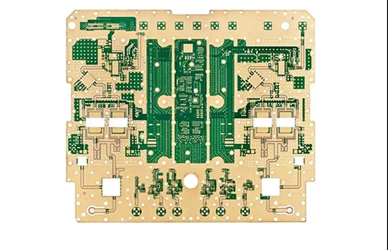
South-Electronic является вашим основным источником высококачественных, надежных и высокоценных высокочастотных печатных плат. Испытайте наш комплексную услугу по проектированию высокочастотных печатных плат - от концепции до завершения, мы гарантируем точность, надежность и строгое соблюдение отраслевых стандартов.
Почему выбрать South-Electronic?
-
Точность и качество
В South-Electronic мы обеспечиваем точность и надежность каждой высокочастотной печатной платы, которую мы производим, гарантируя, что ваши продукты безупречны и работают точно так, как ожидается.
-
Гибкая настройка
Мы адаптируем наши услуги к вашим конкретным требованиям, будь то односторонняя, двусторонняя или сборка BGA. Каковы бы ни были ваши потребности, вы можете масштабировать свои заказы с гибкостью, сохраняя при этом неизменное качество.
-
Быстрый оборот
Мы понимаем, что время имеет решающее значение для вашего бизнеса. Поэтому наши высокоэффективные производственные линии обеспечивают быструю доставку ваших заказов, giúpая вам оставаться впереди сроков и поддерживать ваши проекты на правильном пути.
-
Опытная команда
Когда вы работаете с нами, вы поддерживаетесь командой с годами опыта в сборке печатных плат. Вы получите пользу от уверенности в работе с профессионалами, которые понимают вашу отрасль и знают, как удовлетворить ваши конкретные потребности.
-
Однооконное решение
От первоначального дизайна до окончательной сборки мы заботимся о каждом шаге процесса. С нами вы получаете удобство полноценного партнера, который может xử lýть все ваши потребности в печатных платах без проблем, давая вам мир и упрощая ваш рабочий процесс.
-
Нет минимальных требований к заказу
У вас есть свобода заказать ровно то, что вам нужно, независимо от количества. Даже если это всего одна единица, мы здесь, чтобы удовлетворить ваши требования без каких-либо ограничений на минимальный заказ, давая вам полную гибкость в ваших решениях о покупке.
Связанные проекты, которые мы выполнили
Отзывы клиентов
Общие вопросы
Самые популярные вопросы
Отправьте нам сообщение
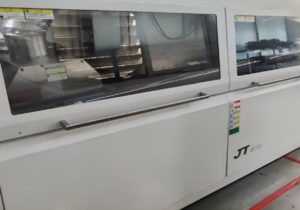
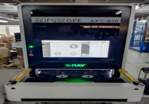

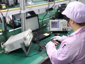

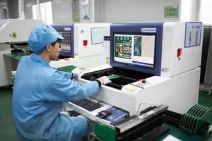










Полное руководство по проектированию высокочастотных печатных плат
Содержание
Глава 1
Введение в высокочастотные ПЛАТ
Что такое высокочастотные ПЛАТ?
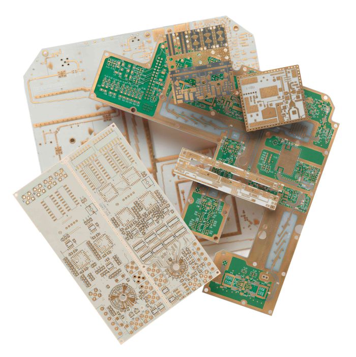
Высокочастотные ПЛАТ не являются обычными платами; они специально разработаны для работы в средах, где требуется быстрая и надежная передача сигналов. Эти платы обычно изготавливаются из материалов с низкими диэлектрическими потерями, таких как FR-4 или политетрафторэтилен (ПТФЭ), что помогает поддерживать целостность сигнала даже на высоких скоростях. Это означает, что они могут обрабатывать быстрое включение-выключение цифровых сигналов и беспрепятственную передачу аналоговых сигналов между различными электронными устройствами.
Почему высокочастотные ПЛАТ так важны?
В сегодняшнем технологически развитом мире важность высокочастотных ПЛАТ нельзя переоценить. Они являются основой многих приложений, которые вы используете каждый день. От систем Wi-Fi и GPS в вашем смартфоне до более сложных систем, таких как радар и спутниковая связь, эти ПЛАТ обеспечивают работу устройств с необходимой точностью и скоростью в эпоху высоких ставок цифровых технологий.
Более того, по мере того, как растет спрос на более быстрые и надежные электронные устройства, роль высокочастотных ПЛАТ становится еще более важной. Они являются ключом к инновациям в области телекоммуникаций, обороны, аэрокосмической промышленности и потребительской электроники, где они способствуют достижениям в технологиях, которые расширяют границы того, что возможно.
Выбирая высокочастотные ПЛАТ, вы не только обеспечиваете себе превосходную электронную производительность, но и инвестируете в будущее технологий. Эти ПЛАТ находятся на переднем крае современной электроники, стимулируя прогресс в бесчисленных отраслях промышленности, обеспечивая более быструю, надежную и эффективную электронную связь. Независимо от того, разрабатываете ли вы передовые потребительские электронные устройства или сложные аэрокосмические системы, высокочастотные ПЛАТ предлагают вам необходимые возможности для успеха в современном технологическом ландшафте.
Глава 2
Материалы и субстраты для высокочастотных ПЛИС
Когда вы начинаете работать с высокочастотным проектированием ПЛИС, выбор материалов и субстратов становится критически важным. Производительность ваших ПЛИС на высоких частотах зависит от этих фундаментальных компонентов. Выбор правильных материалов не仅 важен для обеспечения функциональности, но и для максимизации эффективности, целостности сигнала и общей производительности ваших электронных устройств.
Какие материалы используются в высокочастотных ПЛИС?
Высокочастотным ПЛИС требуются материалы с исключительными электрическими свойствами для обработки быстрого распространения сигналов без значительных потерь. Вот некоторые из наиболее часто используемых материалов в высокочастотных ПЛИС:
- ПТФЭ (Политетрафторэтилен): Известный под брендами как Teflon®, ПТФЭ известен своим низким диэлектрическим коэффициентом и низким коэффициентом диссипации, которые важны для минимальных потерь сигнала на высоких частотах. Это основной материал для применений, требующих превосходной микроволновой производительности.
- FR-4: Хотя стандартный FR-4 является общим материалом для применений с более низкими частотами, высокопроизводительные марки FR-4 доступны, которые предлагают улучшенные диэлектрические свойства для умеренно высокочастотных применений. Это делает FR-4 экономически эффективным вариантом, когда не требуется экстремальная производительность.
- Материалы Rogers: Эти субстраты специально разработаны для высокочастотных ПЛИС. Материалы Rogers, такие как RO4003C и RO4350B, обеспечивают более низкие диэлектрические потери, лучший контроль импеданса и тепловые характеристики, что делает их идеальными для требовательных применений в аэрокосмической, телекоммуникационной и автомобильной промышленности.
- Керамические заполненные ламинаты: Эти субстраты включают керамические наполнители для улучшения тепловой проводимости и снижения теплового расширения, что важно для сохранения структурной целостности и производительности ПЛИС на высоких частотах.
Как эти материалы влияют на целостность сигнала и производительность?
Выбор материала субстрата непосредственно влияет на целостность сигнала ваших высокочастотных ПЛИС несколькими способами:
- Диэлектрический коэффициент (Dk): Более низкий диэлектрический коэффициент помогает уменьшить задержку сигнала. Материалы, такие как ПТФЭ, имеют более низкий Dk, что предпочтительно для высокочастотной передачи сигнала, поскольку позволяет более быстрой скорости сигнала с меньшей изменчивостью импеданса.
- Коэффициент диссипации: Также известный как тангенс потерь, этот коэффициент измеряет, сколько электромагнитной энергии теряется из-за внутренних свойств материала субстрата. Материалы с более низкими коэффициентами диссипации, такие как Rogers и ПТФЭ, важны для минимизации потерь энергии в высокочастотных применениях.
- Тепловой контроль: Высокочастотные операции могут генерировать значительное тепло. Материалы, такие как керамические заполненные ламинаты, важны, поскольку они более эффективно рассеивают тепло, сохраняя целостность схемы и ее производительность во времени.
- Размерная стабильность: Материалы, такие как Rogers и керамические заполненные ламинаты, демонстрируют превосходную размерную стабильность под тепловым напряжением, что важно для сохранения плотных допусков в высокочастотных схемах.
Выбор правильных материалов для ваших высокочастотных ПЛИС не仅 важен для соблюдения минимальных требований; это также важно для повышения производительности и надежности вашего готового продукта. Каждый материал имеет свой набор свойств, которые могут либо усилить, либо помешать эффективности вашего высокочастотного проектирования ПЛИС, влияя на все, от скорости и ясности сигнала до теплового контроля и механической стабильности. Поэтому понимание и выбор оптимального субстрата является критическим решением, которое может определить успех ваших высокочастотных электронных применений.
Глава 3

Разработка плат с высокой частотой
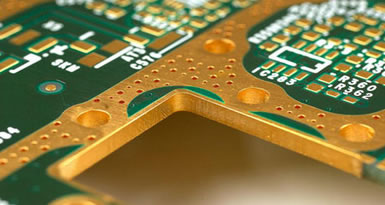
Разработка плат с высокой частотой — это искусство, сочетающее в себе переднюю инженерию и точное выполнение. Когда вы входите в мир разработки плат с высокой частотой, каждое решение, которое вы принимаете, от компоновки до выбора материала, влияет на производительность и надежность окончательного продукта. Давайте углубимся в ключевые факторы проектирования и методы, которые имеют решающее значение для оптимизации приложений с высокой частотой.
Ключевые факторы проектирования для плат с высокой частотой
- Выбор материала: Как мы уже обсуждали, выбор материала является фундаментальным. Для приложений с высокой частотой вам нужны материалы с низкими диэлектрическими постоянными и низкими тангенсами потерь, чтобы улучшить целостность сигнала. Материалы, такие как ПТФЭ (тефлон), Rogers и керамика, заполненные ламинатами, должны быть в верхней части вашего списка. Эти материалы не только поддерживают более высокие частоты, но и минимизируют потери сигнала, обеспечивая прочную базу для ваших проектов.
- Контроль импеданса: В платах с высокой частотой контроль импеданса имеет решающее значение для предотвращения отражения сигналов и потерь передачи. Это предполагает точные расчеты и корректировки ширины и расстояния между следами, в зависимости от диэлектрических свойств субстрата. Достижение последовательного импеданса требует тщательных методов проектирования и часто сотрудничества с поставщиками материалов, чтобы обеспечить соблюдение спецификаций.
- Геометрия следа: Форма и компоновка следов существенно влияют на производительность. Используйте гладкие, изогнутые следы вместо угловых, чтобы минимизировать отражение сигнала и перекрестные помехи. Кроме того, толщина следа должна быть оптимизирована, чтобы сбалансировать сопротивление, индуктивность и емкость, что имеет решающее значение для поддержания целостности сигнала на высоких частотах.
Методы минимизации потерь сигнала и улучшения надежности
- Использование плоскостей земли: Реализация сплошных плоскостей земли под слоями сигналов может существенно уменьшить электромагнитные помехи (ЭМП) и обеспечить стабильный уровень опорного напряжения, который необходим для поддержания целостности сигнала. Плоскости земли также помогают в рассеивании тепла, добавляя к общей надежности платы.
- Экранизация и охраняющие следы: Чтобы еще больше защитить от ЭМП и внешнего шума, рассмотрите возможность использования методов экранизации. Металлическая экранизация может быть включена над чувствительными областями платы. Кроме того, охраняющие следы с виас, подключенными к земле, могут быть использованы вокруг следов с высокой частотой, чтобы изолировать их от других компонентов схемы.
- Тепловой менеджмент: Высокие частоты могут привести к увеличению тепловых нагрузок, поэтому эффективный тепловой менеджмент имеет решающее значение. Разрабатывайте платы с тепловыми облегчениями и радиаторами, если необходимо. Кроме того, выбор материалов с хорошей теплопроводностью может помочь более эффективно рассеивать тепло, сохраняя целостность и долговечность схемы.
- Проектирование виас: В платах с высокой частотой проектирование виас играет значительную роль. Используйте слепые и погружные виас, чтобы уменьшить путь передачи сигнала, тем самым минимизируя ухудшение сигнала. Размещение и размер виас должны быть тщательно спланированы, чтобы избежать разрывов импеданса.
- Размещение компонентов: Стратегическое размещение компонентов является необходимым, чтобы минимизировать длину пути для критических сигналов, тем самым уменьшая возможности потерь сигнала и помех. Компоненты должны быть расположены так, чтобы оптимизировать поток сигнала и минимизировать пересечение путей с высокой частотой, которые могут ввести шум и потерю.
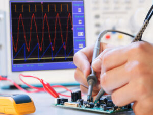
- Тестирование и прототипирование: Всегда прототипируйте свои проекты перед полным производством. Тестирование ваших прототипов позволяет вам выявить и исправить проблемы, связанные с целостностью сигнала и функциональностью. Этот шаг имеет решающее значение для обеспечения того, чтобы ваш проект не только соответствовал желаемым спецификациям, но и работал надежно в реальных приложениях.
Тщательно рассматривая эти факторы проектирования и используя эти методы, вы можете существенно улучшить производительность и надежность своих плат с высокой частотой. Каждое решение в процессе проектирования является шагом на пути к созданию продукта, который не только соответствует, но и превышает строгие требования приложений с высокой частотой.
Глава 4
Целостность и управление сигналом
Когда вы проектируете высокочастотные ПЛІС, вы сталкиваетесь с задачей поддержания целостности сигнала. Целостность сигнала — это жизнь вашего электронного устройства. Это то, что гарантирует, что сигналы, которые вы передаете по вашей ПЛІС, не искажаются и не нарушаются. По мере перехода на более высокие частоты целостность сигнала становится еще более важной и труднее управлять ею. Давайте поговорим о некоторых проблемах и практиках поддержания целостности сигнала, чтобы ваши устройства работали так, как они должны.
Проблемы поддержания целостности сигнала на высоких частотах
- Ослабление сигнала: По мере увеличения частоты потеря сигнала становится более выраженной из-за внутренних свойств материалов и конструкции ПЛІС. Это может привести к более слабым сигналам на стороне приемника, что влияет на общую производительность вашего электронного устройства.
- Отражение и перекрестная связь: Неправильное согласование импеданса и тесно упакованные следы могут привести к отражению сигнала и перекрестной связи между каналами. Эти явления не только ухудшают качество сигнала, но также могут вызвать коррупцию данных и потерю информации.
- Электромагнитные помехи (ЭМП): Высокочастотные схемы более восприимчивы к внешним и внутренним источникам шума, которые могут вызывать нежелательные сигналы и нарушать нормальную работу. Управление ЭМП имеет решающее значение для поддержания целостности высокочастотных сигналов.
Решения и практики для управления целостностью сигнала
- Осторожный выбор материалов: Выбор правильного субстратного материала — это ваша первая линия обороны в обеспечении целостности сигнала. Материалы с низкими диэлектрическими константами и низкими факторами рассеяния, такие как ПТФЭ или субстраты Rogers, идеальны, поскольку они минимизируют потерю сигнала и поддерживают более высокую скорость передачи сигнала.
- Контроль импеданса: Поддержание равномерного импеданса на протяжении всей вашей ПЛІС имеет решающее значение. Это предполагает проектирование геометрии следов и использование контролируемых диэлектрических материалов для согласования импеданса источника и нагрузки. Используйте калькуляторы импеданса и программное обеспечение для моделирования, чтобы смоделировать и доработать ваши проекты для оптимальной производительности.
- Стратегическое маршрутизация следов: Минимизируйте перекрестную связь и отражение, маршрутизируя критические высокочастотные сигналы на отдельных слоях или используя экранированные следы. Используйте дифференциальное сигнализирование, где это возможно, поскольку оно помогает отменить шум и улучшить целостность сигнала.
- Использование плоскостей земли: Включайте сплошные и непрерывные плоскости земли в ваш проект ПЛІС. Плоскости земли уменьшают площадь петли и обеспечивают путь возврата тока, значительно снижая риск ЭМП и отражения сигнала.
- Декуплирование и фильтрация: Размещайте декуплирующие конденсаторы рядом с питательными выводами активных компонентов, чтобы стабилизировать колебания питания и уменьшить шум. Кроме того, используйте методы фильтрации, чтобы исключить нежелательные высокочастотные компоненты из ваших сигналов.
- Усложненное тестирование и моделирование: Используйте передовые инструменты моделирования, чтобы предсказать и проанализировать поведение сигнала до физического прототипирования. Моделирование может помочь выявить потенциальные проблемы, такие как эффекты ЭМП, несоответствия импеданса и отражение сигнала, позволяя вам внести необходимые коррективы на ранней стадии проектирования.
- Регулярные обзоры и итеративное проектирование: Примите практику регулярных обзоров проекта и итеративных улучшений. Оценка вашего проекта на разных стадиях позволяет выявить и исправить проблемы, связанные с целостностью сигнала, повышая надежность и производительность готового продукта.
Понимая эти проблемы и реализуя эти практики, вы можете значительно улучшить целостность сигнала ваших высокочастотных проектов ПЛІС. Помните, каждое решение, которое вы принимаете — от выбора материала до маршрутизации следов — влияет на то, как хорошо ваш продукт работает в реальных приложениях. Обеспечение идеальной целостности сигнала не только означает соответствие техническим спецификациям, но и означает поставку продукта, который выделяется своей надежностью и высокими показателями производительности.
Глава 5
Слоистость и конфигурация слоев
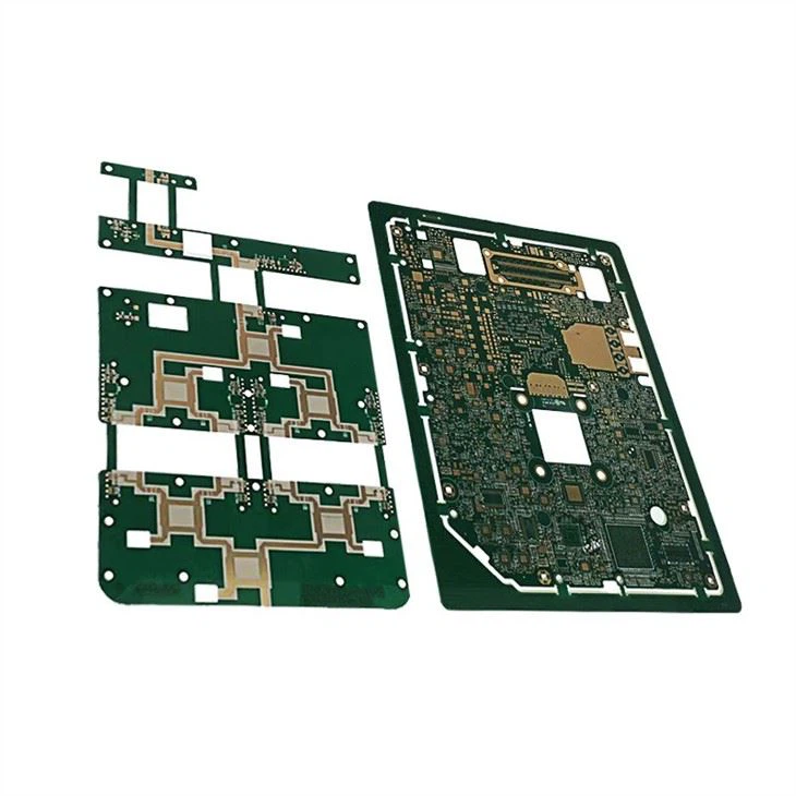
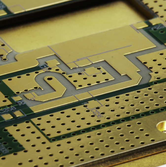
Когда вы начинаете работать с высокочастотными платами, вам необходимо понять, насколько важна слоистость и конфигурация слоев. То, как вы укладываете и конфигурируете слои вашей платы, не только влияет на процесс изготовления, но и на производительность готового продукта. Давайте посмотрим, как эффективные конфигурации слоистости могут оптимизировать ваши высокочастотные платы и какие преимущества оният.
Почему слоистость важна?
Слоистость относится к расположению медных и изоляционных слоев на плате. В высокочастотных приложениях эта конфигурация важна, поскольку она влияет на все, от целостности сигнала и контроля импеданса до управления теплом и экранирования электромагнитных помех (ЭМП). Оптимизированная слоистость обеспечивает, что высокочастотные сигналы передаются с минимальными потерями и помехами, что делает ее краеугольным камнем успешного проектирования плат.
Изучение эффективных конфигураций слоистости
- Стандартная многослойная слоистость: это распространенная конфигурация, которая чередует сигнальные и заземляющие слои. Для высокочастотных плат важно иметь сигнальные слои, тесно связанные с заземляющими слоями, чтобы минимизировать площадь контура сигнала и снизить риск ЭМП. Это помогает сохранить чистоту передачи сигнала и улучшает общую электромагнитную совместимость (ЭМС).
- Симметричная слоистость: симметричная слоистость может быть особенно полезной в высокочастотных конструкциях. Эта конфигурация зеркально отражает расположение слоев вокруг центрального ядра, что помогает сбалансировать общую структуру платы, снизить коробление во время изготовления и сохранить последовательную электрическую производительность на протяжении всей платы.
- Слоистость с высокой плотностью соединений (HDI): технология HDI использует более мелкие расстояния и линии, меньшие переходы и более плотное размещение компонентов. Для высокочастотных приложений слоистости HDI могут значительно сократить длину пути сигнала, улучшая целостность сигнала и снижая перекрестные помехи. Кроме того, HDI позволяет создавать более компактные конструкции, что важно в современных электронных устройствах с ограниченным пространством.
Преимущества различных методов слоистости
- Улучшенный контроль импеданса: при тщательном планировании слоистости можно достичь точного контроля импеданса, что важно для передачи высокочастотных сигналов. Правильно конфигурируя толщину и расстояние между слоями, можно сохранить последовательный уровень импеданса на протяжении всей платы, снижая отражения и потери сигнала.
- Улучшенная целостность сигнала: эффективная слоистость снижает вероятность перекрестных помех и ослабления сигнала. Разделяя высокоскоростные сигнальные слои от потенциальных источников шума и используя заземляющие слои в качестве экранов, вы обеспечиваете, что ваши сигналы остаются сильными и чистыми на протяжении пути передачи.
- Лучшее управление теплом: слоистость может влиять на то, как тепло распределяется и рассеивается на плате. Стратегически размещая тепловые слои или слои теплоотвода, вы можете управлять теплом, генерируемым высокочастотными операциями, защищая чувствительные компоненты и улучшая надежность платы.
- Повышенная долговечность и надежность: хорошо спланированная слоистость способствует физической стабильности платы. Она помогает управлять механическими напряжениями и снижает вероятность структурных неисправностей, таких как отслоение или растрескивание, что критически важно в высокочастотных приложениях, где важна целостность материала.
- Оптимизация использования пространства: особенно в конструкциях HDI, эффективные конфигурации слоистости позволяют максимально использовать доступное пространство платы. Это важно, когда необходимо упаковать больше функциональности в более компактные устройства, что является общим требованием в современных высокотехнологичных приложениях.
Освоив искусство слоистости и конфигурации слоев, вы не только улучшаете производительность и надежность своих высокочастотных плат, но и закладываете основу для инноваций, которые удовлетворяют требованиям технологического ландшафта завтрашнего дня. Помните, каждый слой в вашей слоистости играет критическую роль, и понимание того, как эффективно конфигурировать их, может быть ключом к раскрытию полного потенциала ваших высокочастотных конструкций.
Глава 6
Управление импедансом и согласование
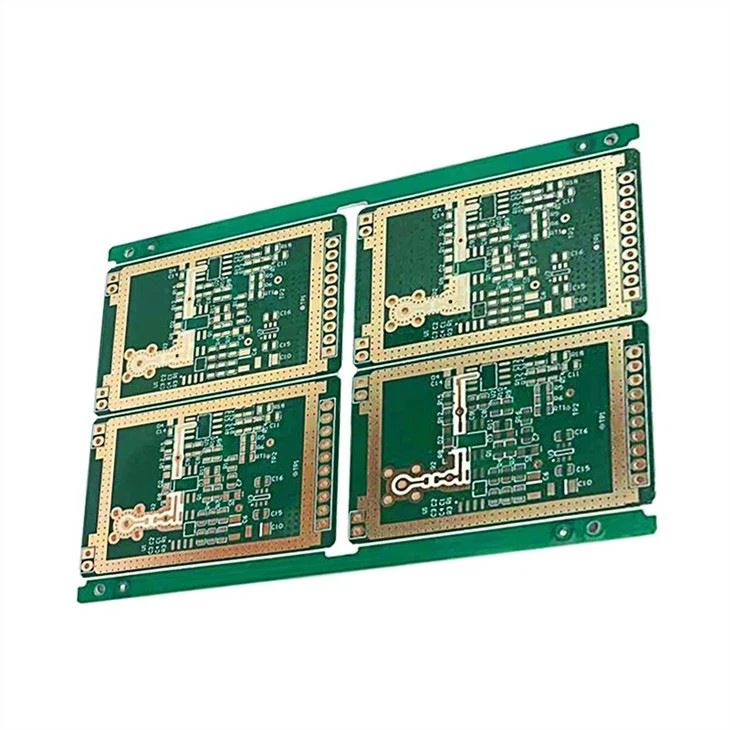
Когда вы переходите в область проектирования высокочастотных плат, одним из наиболее важных аспектов, которые необходимо освоить, является управление импедансом и согласование. Это не просто техническая необходимость — это основной фактор, который обеспечивает оптимальную работу вашей платы, предотвращая ухудшение сигнала и обеспечивая надежную связь между компонентами. Давайте погрузимся в то, почему управление импедансом так важно и как вы можете достичь и поддерживать идеальное согласование импеданса по всей плате.
Почему управление импедансом так важно в высокочастотных платах?
Управление импедансом является необходимым, поскольку оно напрямую влияет на целостность и производительность сигналов, проходящих через вашу плату. В высокочастотных приложениях любое несоответствие импеданса может привести к отражению сигналов, стоячим волнам и потере целостности сигнала, что может ухудшить производительность всей системы. Эффективное управление импедансом обеспечивает гладкое распространение электрических сигналов без нарушений, обеспечивая последовательную производительность и минимизируя потерю сигнала.
Методы достижения и поддержания согласования импеданса
Выбор материала: Путь к идеальному управлению импедансом начинается с правильного выбора материала. Вам нужны субстраты с постоянными диэлектрическими свойствами, чтобы обеспечить равномерные уровни импеданса по всей плате. Материалы, такие как FR-4, Rogers и Teflon, являются популярными выборами благодаря их стабильным диэлектрическим константам и тангенсам потерь, которые имеют решающее значение для поддержания целостности импеданса на высоких частотах.
Проектирование геометрии следов: Размеры и расположение следов вашей платы играют решающую роль в управлении импедансом. Чтобы согласовать импеданс, необходимо тщательно проектировать ширину, толщину и расстояние между следами в соответствии с диэлектрическими свойствами вашего субстрата и целевым значением импеданса. Инструменты, такие как калькуляторы импеданса и программное обеспечение для решения задач поля, могут помочь вам моделировать и оптимизировать эти параметры эффективно.
Использование плоскостей земли и питания: Реализация непрерывных плоскостей земли и питания под слоями сигналов может значительно улучшить стабильность импеданса. Эти плоскости не только обеспечивают прочную точку отсчета для сигналов, но также помогают уменьшить электромагнитные помехи и перекрестную связь, еще больше стабилизируя импеданс.
Конфигурация стека: Оптимизированная конфигурация слоя может помочь поддерживать постоянный импеданс по всей плате. Убедитесь, что слои сигналов тесно связаны с плоскостями земли и что стэк симметричен, чтобы избежать любых изменений импеданса из-за физических и тепловых напряжений во время изготовления и эксплуатации платы.
Управление импедансом при маршрутизации: При маршрутизации высокочастотных следов поддерживайте постоянный импеданс, избегая внезапных изменений ширины или направления следа, что может привести к разрывам импеданса. Техники, такие как использование изогнутых следов вместо углов и поддержание равномерных расстояний между следами, могут помочь сохранить целостность импеданса.
Техники завершения: Правильное завершение следов имеет решающее значение для согласования импеданса, особенно когда речь идет о высокочастотных сигналах. Используйте техники, такие как последовательное или параллельное завершение, чтобы согласовать импеданс на концах линий передачи, минимизируя отражения и обеспечивая гладкую передачу сигналов.
Регулярное тестирование и верификация: На протяжении всего процесса проектирования и изготовления платы регулярно тестируйте и верифицируйте импеданс с помощью методов TDR (рефлектометрия во временной области) и других методов измерения. Это гарантирует, что импеданс остается в пределах заданных ограничений и что любые проблемы выявляются и исправляются до окончательного производства.
Применяя эти методы, вы гарантируете, что каждый компонент на вашей плате общается эффективно, без опасности несоответствия импеданса. Это не только повышает производительность вашей высокочастотной платы, но также улучшает надежность и долговечность вашего электронного устройства. Помните, в мире высокочастотной электроники точность в управлении импедансом не является просто вариантом — это необходимость для поддержания конкурентоспособности и достижения технологического совершенства.
Глава 7
Управление Теплом в Печатных Платах Высокой Частоты
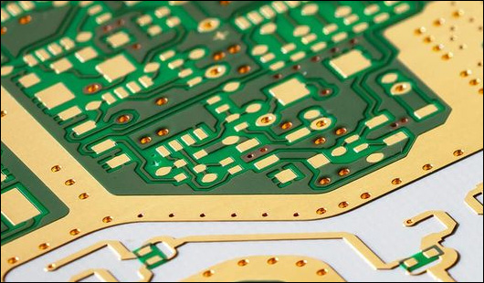
Когда вы начинаете работать с проектированием печатных плат высокой частоты, управление теплом становится большой проблемой. По мере увеличения частоты увеличивается плотность мощности, и это означает, что температура также увеличивается. Это может повлиять на надежность и производительность ваших электронных устройств. Поэтому давайте поговорим о проблемах и о том, как с ними можно справиться, чтобы ваши печатные платы высокой частоты работали так, как вам нужно.
Проблемы Управления Теплом в Печатных Платах Высокой Частоты
Увеличенная Плотность Мощности: Высокочастотные операции часто требуют компонентов, которые потребляют больше мощности, что приводит к увеличению генерации тепла на единицу площади. Это может создать горячие точки на печатной плате, что вредно как для электронных компонентов, так и для субстрата.
Чувствительность Компонентов: Многие компоненты высокой частоты чувствительны к изменениям температуры. Чрезмерное тепло может привести к ускоренному старению, снижению производительности и даже выходу компонентов из строя, что компрометирует общую функциональность устройства.
Ограничения Материалов: Субстраты и материалы, используемые в печатных платах высокой частоты, такие как ПТФЭ или высокопроизводительные ламинаты, имеют конкретные тепловые характеристики. Некоторые материалы могут не рассеивать тепло так эффективно, как необходимо, что может привести к накоплению температуры и увеличению теплового напряжения.
Компактные Макеты: По мере уменьшения размеров устройств и увеличения спроса на более компактные электронные продукты увеличивается плотность упаковки компонентов на печатных платах. Этот более плотный макет еще больше усложняет эффективное рассеивание тепла.
Стратегии Эффективного Управления Теплом
Выбор Материалов: Начните с выбора правильных материалов субстрата, которые не только соответствуют вашим электрическим требованиям, но и имеют хорошую теплопроводность. Материалы, такие как металлические печатные платы (МСП), которые включают металлический слой (обычно алюминий или медь) под термическими подушками критических компонентов, могут существенно помочь в рассеивании тепла.
Термические Виасы: Реализуйте термические виасы для эффективной передачи тепла с верхнего слоя, где установлены компоненты, на нижние слои или на противоположную сторону печатной платы, которые затем могут более эффективно рассеивать тепло. Эти виасы действуют как небольшие тепловые трубы, распределяя тепло по более большой площади для уменьшения горячих точек.
Радиаторы и Системы Охлаждения: Присоедините радиаторы непосредственно к компонентам, генерирующим тепло, или используйте бортовые системы охлаждения, такие как вентиляторы или жидкостные системы охлаждения. Они особенно полезны в высокомощных приложениях, где пассивное охлаждение может быть недостаточным.
Размещение Компонентов и Оптимизация Макета: Тщательно спланируйте размещение компонентов, чтобы минимизировать тепловое взаимодействие и избежать создания горячих точек. Обеспечьте достаточное расстояние между компонентами высокой мощности, чтобы обеспечить адекватную циркуляцию воздуха и рассеивание тепла. Используйте инструменты моделирования во время фазы проектирования для моделирования тепловых характеристик и корректировки макетов по мере необходимости.
Термические Подушки: Используйте термические подушки, чтобы помочь управлять соединением компонентов, генерирующих тепло, с землей или силовыми плоскостями. Эти подушки могут предотвратить чрезмерную передачу тепла к другим частям печатной платы, которые могут быть чувствительны к изменениям температуры.
Регулярное Тепловое Тестирование: Проводите тепловое тестирование во время прототипирования и фаз производства, чтобы понять, как ваша печатная плата работает при эксплуатационных условиях. Используйте инфракрасные камеры, термопары и другие устройства для обнаружения температуры, чтобы определить горячие точки и тепловые градиенты, и усовершенствуйте ваш проект на основе этих результатов.
Включая эти стратегии в процесс проектирования печатных плат, вы можете эффективно управлять тепловыми проблемами, возникающими при высокочастотных операциях. Хорошее управление теплом не только повышает долговечность и надежность ваших печатных плат высокой частоты, но и гарантирует, что ваши устройства функционируют в безопасных температурных пределах, сохраняя срок службы и производительность каждого компонента на плате. Помните, эффективное управление теплом — это не только поддержание компонентов в прохладном состоянии; это обеспечивает бесперебойную работу всей системы при оптимальных температурах.
Глава 8
Тестирование и прототипирование для высокочастотных ПЛИС
Когда вы разрабатываете высокочастотные ПЛИС, фазы тестирования и прототипирования не являются просто шагами в процессе — они являются вашей гарантией качества и надежности до начала полномасштабного производства. Эти стадии позволяют вам выявить потенциальные проблемы и оптимизировать ваш дизайн, гарантируя, что ваши ПЛИС соответствуют как вашим стандартам, так и стандартам отрасли. Давайте рассмотрим необходимые тесты и методы прототипирования, которые имеют решающее значение для высокочастотных ПЛИС, и проведем вас через процесс того, как сделать эти шаги краеугольным камнем вашего дизайна.
Необходимые тесты для высокочастотных ПЛИС
Тестирование во временной области (TDR): Этот тест необходим для измерения характеристик импеданса вашей ПЛИС. Тестирование TDR помогает вам обнаружить любые разрывы импеданса, которые могут вызвать отражение сигналов, что важно для поддержания целостности сигнала на высоких частотах.
Тесты целостности сигнала: Проведите тесты для анализа качества сигналов на вашей ПЛИС. Эти тесты включают измерение параметров, таких как время подъема и спада, джиттер и диаграммы глаза, гарантируя, что сигналы сильны и четки без помех, даже на высоких частотах.
Тестирование электромагнитной совместимости (EMC): Чтобы гарантировать, что ваша высокочастотная ПЛИС не излучает нежелательные электромагнитные помехи (EMI) или не подвержена внешним EMI, тестирование EMC является критически важным. Это помогает вам проверить, что ваша ПЛИС соответствует международным стандартам EMC, что важно для признания на рынке.
Термическое тестирование: Поскольку высокочастотные операции могут генерировать значительное тепло, проведение термических тестов с помощью термографических камер или датчиков является необходимым. Это гарантирует, что ваши стратегии термического управления эффективны и что ваша ПЛИС может работать надежно при различных температурных условиях.
Тестирование целостности питания: Оцените производительность сети распределения питания (PDN) на вашей ПЛИС, чтобы гарантировать, что все компоненты получают стабильное и чистое питание без чрезмерного шума или падения напряжения, что критически важно для надежной работы высокочастотных компонентов.
Методы прототипирования и их важность
Быстрое прототипирование: Используйте методы, такие как обработка на станках с ЧПУ, чтобы быстро произвести прототипы ПЛИС. Это позволяет вам быстро изменять дизайн на основе обратной связи от тестирования, что значительно ускоряет процесс разработки.
3D-печать ПЛИС: Для очень сложных или нестандартных дизайнов можно использовать 3D-печать для прототипирования ПЛИС, что позволяет добиться большей гибкости в дизайне и возможности тестирования форм-факторов, которые трудно создать традиционными методами.
Низкообъемная производство: Перед переходом к массовому производству изготовление небольшой партии ПЛИС может быть бесценным. Этот низкообъемный выпуск может быть использован для обширного функционального тестирования и сбора обратной связи от потенциальных пользователей или полевых испытаний.
Почему прототипирование и тестирование имеют решающее значение
Снижение риска: Раннее и итеративное прототипирование в сочетании с тщательным тестированием значительно снижает риск неудач в полномасштабном производстве. Это помогает выявить и исправить дефекты дизайна и гарантирует, что конечный продукт соответствует необходимым спецификациям.
Экономическая эффективность: Выявление проблем на стадии прототипирования намного менее дорого, чем внесение изменений в процессе полномасштабного производства или, что еще хуже, отзыв дефектной продукции с рынка.
Оптимизация производительности: Тестирование и прототипирование предоставляют вам возможность тонко настроить производительность ваших ПЛИС, гарантируя, что они работают с максимальной эффективностью и оптимизированы для своей предполагаемой области применения.
Уверенность заинтересованных сторон: Демонстрация тщательно протестированных и прототипированных ПЛИС строит доверие среди заинтересованных сторон, включая инвесторов, клиентов и регулирующие органы, что продукт надежен и готов к выходу на рынок.
Включая всестороннее тестирование и прочное прототипирование в свой процесс разработки, вы гарантируете, что ваши высокочастотные ПЛИС не только функциональны, но и являются отшлифованными машинами, готовыми встретить вызовы техноинтенсивных сред, в которых они будут работать. Помните, эти шаги являются вашими лучшими инструментами для минимизации рисков и совершенствования ваших продуктов до их выхода на рынок.

Глава 9
Процессы производства для высокочастотных ПЛІС
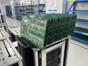
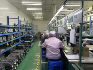
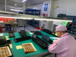
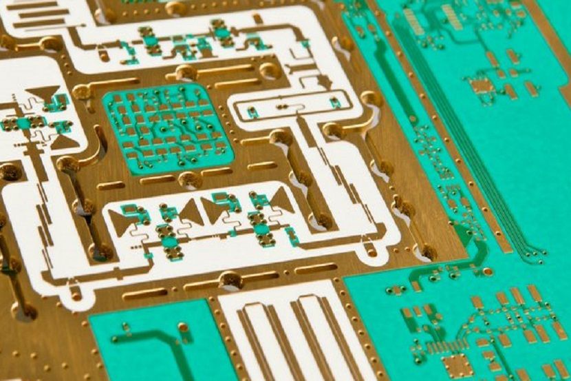
Когда вы углубляетесь в производство высокочастотных ПЛІС, вы входите в область, где точность и соблюдение стандартов качества не просто являются целями, они являются необходимостью. Каждый шаг в производственном процессе играет решающую роль в определении производительности и надежности вашего окончательного продукта. Понимание нюансов этих процессов и того, как разные техники влияют на результат, имеет решающее значение. В этой статье мы рассмотрим сложный мир производства высокочастотных ПЛІС, проводя вас через каждый шаг и его влияние на окончательную ПЛІС.
Обзор производственного процесса для высокочастотных ПЛІС
Выбор материала: Путешествие начинается с выбора правильных материалов. Для высокочастотных ПЛІС предпочтительны материалы, такие как ПТФЭ, Роджерс и керамика, наполненные ламинатами, благодаря их низким диэлектрическим постоянным и тангенсам потерь, которые необходимы для минимизации потерь сигнала и обеспечения целостности сигнала на высоких частотах.
Печать схемы: Дизайн вашей высокочастотной ПЛІС переносятся на выбранный субстрат с помощью передовых методов печати. Это может включать фотолитографию, при которой применяется фотоотиститель и облучается светом для создания схемы, или методы прямого изображения для более сложных или тонких дизайнов.
Травление: После печати схемы нежелательная медь удаляется посредством травления. Точность на этом этапе имеет решающее значение; любое отклонение может повлиять на импеданс и производительность высокочастотных сигналов. Используются контролируемые методы травления для обеспечения того, чтобы только нежелательная медь была растворена, в результате чего получается чистая и точная схема.
Слоистость и ламинирование: Многослойные ПЛІС укладываются и ламинируются под воздействием тепла и давления. Для высокочастотных ПЛІС обеспечить идеальное совпадение каждого слоя имеет решающее значение для поддержания целостности электрических путей и эффективного контроля импеданса. Любое несоответствие может привести к проблемам с целостностью сигнала и снижению производительности.
Сверление и покрытие: Сверлятся отверстия или виасы для установления соединений между разными слоями ПЛІС. Для высокочастотных применений точность установки виасов и качество покрытия внутри виасов имеют первостепенное значение. Эти виасы должны быть идеально выровнены и иметь гладкое медное покрытие для обеспечения надежных электрических соединений и поддержания целостности сигнала.
Нанесение защитного слоя пайки: Защитный слой пайки наносится поверх медных следов для защиты их от окисления и предотвращения мостов пайки во время установки компонентов. Для высокочастотных ПЛІС защитный слой пайки должен быть нанесен равномерно, чтобы избежать любых непреднамеренных емкостных или изоляционных проблем.
Окончательная отделка поверхности: ПЛІС получает окончательную отделку поверхности, которая служит защитным покрытием и обеспечивает надежную паяемую поверхность для установки компонентов. Выбираются варианты, такие как ENIG (электролесс никель погружение золота) или HASL (горячий воздух пайка уровня), исходя из их влияния на целостность сигнала и их совместимости с высокочастотными приложениями.
Тестирование и контроль качества: Каждая высокочастотная ПЛІС проходит строгие тесты, включая испытания на импеданс, тесты целостности сигнала и проверки функциональности. Эти тесты обеспечивают соответствие каждой ПЛІС жестким требованиям, необходимым для высокочастотных операций.
Влияние различных методов производства на окончательный продукт
Передовая обработка материалов: Использование специализированных материалов, таких как ПТФЭ, требует корректировки стандартных процессов производства ПЛІС, таких как измененные методы травления и ламинирования для обработки этих чувствительных материалов без повреждения их свойств.
Точная инженерия: Требование высокой точности при травлении, сверлении и выравнивании слоев усиливается при производстве высокочастотных ПЛІС. Небольшие отклонения могут значительно повлиять на производительность, что делает точную инженерию краеугольным камнем процесса.
Специализированные методы отделки: Выбор отделки поверхности имеет более выраженное влияние на высокочастотные ПЛІС, поскольку некоторые отделки могут ввести нежелательную индуктивность или емкость. Выбор правильной отделки имеет решающее значение для поддержания оптимальной производительности сигнала.
Освоив эти производственные процессы и поняв их последствия, вы обеспечиваете, что ваши высокочастотные ПЛІС не только функционируют так, как предполагалось, но и выдерживают требования современных электронных применений. Каждый шаг, от выбора материала до окончательного тестирования, направлен на достижение высочайшего качества и производительности, обеспечивая, что ваши ПЛІС работают там, где это наиболее важно.
Глава 10
Будущие тенденции в проектировании ПЛИС высоких частот
Когда мы смотрим на горизонт проектирования ПЛИС высоких частот, становится ясно, что эта область готова к трансформационным изменениям. Новые технологии и материалы создают условия для революционных достижений, которые изменят то, как мы проектируем и используем ПЛИС в приложениях высоких частот. Давайте рассмотрим, что эти тенденции включают в себя и предскажем, как они могут повлиять на будущий ландшафт технологии ПЛИС.
Новые технологии и материалы
Подложки из жидкокристаллического полимера (ЛКП): Жидкокристаллический полимер привлекает внимание в качестве материала подложки для ПЛИС высоких частот благодаря своим отличным электрическим свойствам, включая низкую диэлектрическую постоянную и тангенс угла потерь, которые необходимы для минимальных потерь сигнала и максимальной целостности сигнала. ЛКП также высоко устойчив к влаге и имеет превосходную термическую стабильность, что делает его идеальным для экстремальных сред.
Интегрированные пассивные устройства (ИПУ): Интеграция пассивных компонентов непосредственно на подложку ПЛИС является растущей тенденцией. ИПУ помогают уменьшить размер и вес сборок ПЛИС, повышают целостность сигнала за счет минимизации соединений и улучшают надежность за счет уменьшения количества паяных соединений. Эта технология особенно полезна в приложениях высоких частот, таких как телекоммуникации и аэрокосмическая промышленность.
Электроника, напечатанная методом 3D-печати: Аддитивное производство или 3D-печать готова революционизировать производство ПЛИС, позволяя создавать более сложные геометрии и многомерные структуры. Эта технология позволяет интегрировать электронную функциональность в саму ткань компонентов, открывая новые пути для миниатюризации устройств и сложных приложений высоких частот.
Гибкие и растяжимые ПЛИС: По мере роста спроса на носимую технологию и гибкую электронику растет и потребность в ПЛИС, которые могут изменять свою форму и растягиваться. Разрабатываются новые материалы и методы изготовления для производства гибких ПЛИС высоких частот, способных поддерживать производительность под механическим напряжением и деформацией.
Прогнозы того, как эти достижения сформируют будущее
Большая интеграция и миниатюризация: Будущее проектирования ПЛИС высоких частот, вероятно, будет характеризоваться еще более компактными и интегрированными решениями. Технологии, такие как ИПУ и 3D-печать, позволят разработчикам встраивать больше функциональности в меньшие площади, расширяя пределы миниатюризации при улучшении производительности и надежности.
Повышенная производительность в суровых условиях: С материалами, такими как ЛКП, будущие ПЛИС высоких частот будут более долговечными и способными работать в экстремальных условиях. Это будет иметь решающее значение для расширения использования электроники высоких частот в таких секторах, как аэрокосмическая, военная и автомобильная промышленность.
Широкое внедрение гибких и растяжимых ПЛИС: Продолжающееся развитие гибких подложек приведет к более широкому внедрению в потребительской электронике, медицинских устройствах и даже в новых областях, таких как мягкая робототехника. Эти ПЛИС не только должны работать на высоких частотах, но и выдерживать изгиб и растяжение, что заставляет разработчиков мыслить за пределами традиционных парадигм проектирования.
Устойчивость в производстве ПЛИС: По мере того, как экологические проблемы становятся более актуальными, промышленность ПЛИС, вероятно, перейдет к более устойчивым производственным процессам. Это может включать использование биоразлагаемых материалов, перерабатываемых подложек и энергоэффективных методов изготовления.
Продвинутые инструменты моделирования и тестирования: По мере увеличения сложности ПЛИС высоких частот продвинутые инструменты моделирования и тестирования станут еще более важными. Эти инструменты должны будут прогнозировать и смягчать проблемы, связанные с электромагнитными помехами, термическим управлением и механическим напряжением, еще до создания физических прототипов.
Оставаясь в курсе этих тенденций, вы не только будете готовиться к будущему проектирования ПЛИС высоких частот, но и формировать его. Каждый прогресс приближает нас к более мощным, эффективным и универсальным электронным устройствам, возвещая новую эру технологий, которая преодолевает ограничения сегодняшнего дня
Связаться с Нами
Где Мы Находимся?
Промышленный Парк, № 438 Донхуан Роад, № 438, Шадзин Донхуан Роад, Район Баоань, Шэньчжэнь, Гуандун, Китай
4-й Этаж, Креативное Здание Жихуй, №2005 Сихуан Роад, Шадзин, Район Баоань, Шэньчжэнь, Китай
Комната A1-13, 3-й Этаж, Промышленный Центр Йи Лим, 2-28 Улица Kвай Лок, Квай Чунг, Гонконг
service@southelectronicpcb.com
Телефон: +86 400 878 3488
Отправьте нам сообщение


