
Copper Core PCB Supplier
South-Electronic
Go with South-Electronic for the best quality, reliability, and value in your PCB needs. You’ll see the difference with our complete Copper Core PCB services – from design to production, we make sure you get precision, durability, and compliance with the toughest industry standards.
Your Trusted Supplier of Copper Core PCB
Welcome to South-Electronic! We’re your go-to source for top-notch Copper Core PCBs that are known for their superior heat dissipation and robust performance.
Our Copper Core PCBs are built to last, making them perfect for high-power applications in demanding industries. We offer a variety of configurations, including 2-layer, 4-layer, and even more complex multi-layer boards, all designed to meet your specific electronic needs. Whether you’re looking to boost the functionality of power electronics or need high-performance boards for automotive applications, our Copper Core PCBs are proven to deliver reliability and precision. Count on South-Electronic for consistent, high-quality products for your high-tech projects. Our Copper Core PCBs will improve your devices’ performance with exceptional thermal management and increased durability. Partner with us to achieve innovation and success in your field.
Why Choose South-Electronic?
-
Custom Solutions
Your project is unique, and so are your needs.
At South-Electronic, we get that, which is why we offer custom Copper Core PCB solutions designed specifically for you. You’ll get a product that meets your exact specifications, no compromises. -
Quality Assurance
You care about quality, and so do we.
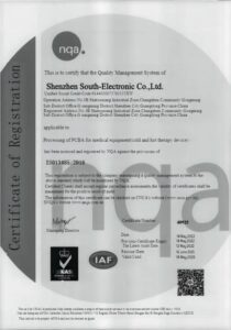
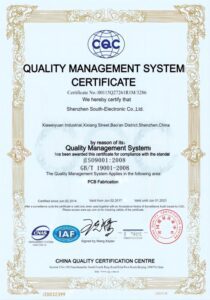
With ISO9001 certification and rigorous testing throughout the production process, you can trust that our Copper Core PCBs will deliver the reliability and longevity your project demands. -
Flexible Ordering
Whether you need a prototype or a large production run, you’re in control.
Our flexible MOQ allows you to order as little as 1 piece, so you can get exactly what you need, when you need it, and at a price that fits your project’s size and budget. -
Professional and Efficient
You’ll benefit from the wealth of experience our team brings.
With years of industry knowledge, we’re here to solve your toughest challenges. From design to delivery, we’ll guide you every step of the way. -
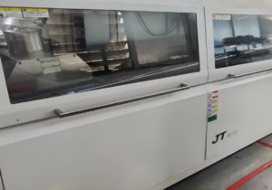
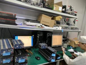
Production Capabilities
Fast Turnaround to Keep You on Schedule.
That’s why we’ve streamlined our production lines to ensure you get your Copper Core PCBs quickly, without sacrificing quality. You’ll have what you need when you need it, keeping your project on track. -
Production Capabilities
You’ll enjoy a one-stop solution from us – from sourcing components to final assembly.
And whether it’s technical support, product updates, or timely communication, you can always count on us to be responsive to your needs.
Related Project We had Done
Customer Reviews
engineer
thank you, guys, the boards are really good, i am really happy to receive my boards, the components are perfect!

Operation Manager
South-Electronic is my first PCBA supplier in China. The service and quality are excellent, and the after-sales support is also very impressive. Good Job!


Common Questions
Most Popular Questions
South-Electronic provides a variety of copper core PCBs, including single-sided and multilayer copper core PCBs designed for high-power applications such as LED lighting, automotive electronics, and heat-dissipating devices.
South-Electronic offers comprehensive one-stop PCB services, including prototyping, PCB manufacturing, assembly, and component sourcing, covering the entire process from design to production.
South-Electronic follows a strict quality control system, adhering to ISO 9001 and IPC standards to ensure that each PCB meets high-quality requirements. Comprehensive functional testing and quality checks are conducted before shipping.
Yes, South-Electronic offers a wide range of customization options, allowing customers to adjust board thickness, copper weight, layers, and special materials to meet specific project requirements.
Typically, South-Electronic’s production lead time ranges from 7 to 15 working days, depending on the complexity and size of the order. Expedited services are also available for urgent projects.
Send us a message
The more detailed you fill out, the faster we can move to the next step.


The Complete Guide For Copper Core PCB
Contents
Chapter 1
Introduction to Copper Core PCB
Copper Core PCBs, also known as copper-based PCBs, are a specialized type of printed circuit board that use a copper substrate to provide better thermal conductivity and improved electrical performance. Unlike traditional PCBs that use fiberglass or other non-metal materials, copper core PCBs are designed to efficiently manage heat dissipation, making them ideal for high-power applications.
As the electronics industry continues to evolve, there is a growing demand for PCBs that can handle higher power densities and thermal management challenges. Copper Core PCBs are increasingly being used in applications such as LED lighting, automotive electronics, and power supplies, where heat dissipation is critical for maintaining performance and extending the lifespan of components.
The key advantages of copper core PCBs over traditional PCBs include better thermal management, greater durability, and the ability to support higher currents. These benefits make copper core PCBs the preferred choice for industries that need reliable, high-performance circuit boards that can handle demanding operational conditions.
By incorporating copper into the PCB design, manufacturers can achieve better heat distribution, reduced hot spots, and improved overall system reliability, especially in high-frequency and high-current environments.
Chapter 2
What is a Copper Core PCB?
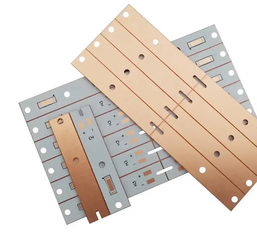
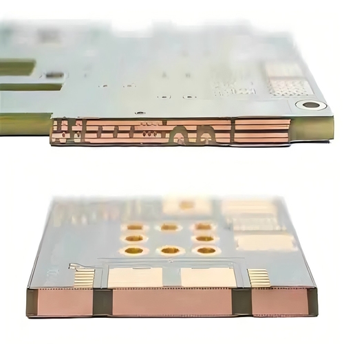
A Copper Core PCB is a type of printed circuit board that incorporates a copper substrate to enhance heat dissipation and improve the overall electrical performance of the board. These PCBs consist of a solid copper core sandwiched between layers of dielectric material and conductive copper layers. The copper core serves as both a thermal conductor and a structural foundation, offering exceptional heat transfer capabilities compared to traditional PCBs.
Structure of a Copper Core PCB
The typical structure of a copper core PCB includes:
- Top Conductive Layer: This is where the electronic components are mounted and connected through copper traces.
- Dielectric Layer: Positioned between the top conductive layer and the copper core, this layer provides electrical insulation while allowing heat to pass through efficiently.
- Copper Core: The central copper layer acts as a heat sink, absorbing and dissipating heat generated by high-power components.
- Bottom Conductive Layer: Optional in some designs, this layer can be used for grounding or additional heat dissipation.
Differences Between Copper Core and Other Metal Core PCBs
While copper core PCBs share similarities with other metal core PCBs (MCPCBs) like aluminum or steel core PCBs, there are distinct differences:
- Thermal Conductivity: Copper has a significantly higher thermal conductivity compared to aluminum or steel, making it more effective for heat management in high-power applications.
- Electrical Conductivity: Copper’s superior electrical conductivity allows for better power distribution and reduced resistance, which is crucial for high-frequency and high-current circuits.
- Cost: Copper core PCBs are generally more expensive than aluminum or steel core PCBs due to the higher cost of copper as a raw material. However, the performance benefits often justify the investment in applications where heat dissipation is critical.
- Weight: Copper is denser and heavier than aluminum, so copper core PCBs tend to weigh more. This can be a consideration for applications where weight is a factor, though it’s often outweighed by performance needs.
Copper Core PCBs are most commonly used in applications where high thermal conductivity and reliable electrical performance are critical, such as in LED lighting, automotive electronics, and power devices. Their ability to manage heat effectively and support high-performance components makes them an essential solution for industries with demanding thermal and electrical requirements.
Chapter 3

Advantages of Using Copper Core PCB
Copper Core PCBs offer several advantages over traditional PCB designs, making them a preferred choice in applications that demand superior thermal management and high reliability. Below are the key benefits:
Superior Thermal Conductivity
One of the primary advantages of copper core PCBs is their exceptional thermal conductivity. Copper, being one of the most efficient materials for heat transfer, allows these PCBs to dissipate heat much faster than PCBs made from standard fiberglass or aluminum cores. This feature is crucial in high-power applications, where excessive heat can lead to component failure, reduced performance, or a shorter product lifespan. The ability of copper core PCBs to manage and spread heat evenly helps maintain optimal operating temperatures for electronic components.
Better Heat Dissipation for High-Power Applications
In industries such as automotive electronics, LED lighting, and power electronics, managing heat is vital for the longevity and efficiency of devices. Copper core PCBs excel at dissipating heat away from critical components, reducing the risk of overheating and improving overall system reliability. This makes copper core PCBs particularly suitable for high-power applications where traditional PCBs may struggle to cope with the heat generated. By efficiently distributing heat, copper core PCBs help maintain the integrity of components and ensure consistent performance over time.
Increased Durability and Reliability
Copper core PCBs not only offer superior thermal performance but also enhance the durability and reliability of the overall circuit design. The copper core provides a strong structural foundation, making the PCB more resistant to thermal stress, mechanical wear, and environmental factors. This increased durability translates to a longer lifespan for devices, reduced maintenance costs, and fewer failures in the field. Additionally, copper’s high conductivity allows for better electrical performance, reducing the chance of signal loss or interference, which is critical in high-frequency applications.
Overall, the combination of excellent heat management, durability, and reliable electrical performance makes copper core PCBs an ideal solution for industries that require high-quality, long-lasting circuit boards capable of withstanding demanding operational conditions.
Chapter 4
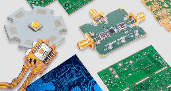
Applications of Copper Core PCBs
Copper Core PCBs are widely used in industries where heat management and electrical performance are critical. Their unique properties make them suitable for a variety of high-power, high-performance applications. Below are some of the key sectors benefiting from copper core technology:
Automotive Electronics
In the automotive industry, many components such as power converters, control modules, and LED headlights generate significant amounts of heat. Copper Core PCBs are essential in these applications because they efficiently dissipate heat, ensuring that sensitive electronic components function reliably even under extreme temperature conditions. The ability to handle high current and heat makes copper core PCBs ideal for electric vehicle systems, motor controllers, and power management units.
LED Lighting
One of the most common applications of Copper Core PCBs is in LED lighting systems. LEDs generate substantial heat, and copper core PCBs are used to manage that heat and prolong the lifespan of the LEDs. By dissipating heat more effectively, copper core PCBs help maintain the brightness and efficiency of LEDs, making them ideal for high-performance lighting solutions in automotive, industrial, and commercial lighting sectors.
Power Electronics
Power electronics systems, such as power supplies, inverters, and converters, often involve high currents and generate a lot of heat. Copper Core PCBs are crucial for these systems as they provide efficient heat dissipation and maintain the integrity of the circuit under heavy electrical loads. In high-power devices like industrial machinery and power distribution systems, copper core technology helps prevent overheating and increases the reliability and longevity of the equipment.
High-Frequency Circuits and High-Current Applications
In high-frequency circuits, copper core PCBs offer better signal integrity and reduced electromagnetic interference (EMI) due to the excellent conductivity of copper. This is particularly important in telecommunications, radar systems, and wireless communication devices. Additionally, copper core PCBs are ideal for high-current applications because they can handle larger electrical loads without experiencing performance degradation or overheating.
Other Industries Benefiting from Copper Core Technology
Apart from automotive, lighting, and power electronics, other industries also benefit from copper core PCBs. In the aerospace and defense sectors, copper core PCBs are used in mission-critical systems where reliability and heat management are paramount. The medical industry also uses copper core PCBs in imaging systems and diagnostic equipment that require stable and long-lasting performance. Furthermore, consumer electronics, including high-performance computing and gaming systems, increasingly rely on copper core technology to manage heat and enhance device longevity.
In summary, Copper Core PCBs play a vital role across a wide range of industries, offering the thermal management, durability, and performance necessary for high-power and high-performance applications.
Chapter 5

Copper Core PCB Manufacturing Process
The manufacturing process of Copper Core PCBs is more complex than traditional PCBs due to the unique thermal and electrical properties of copper. Below is a step-by-step guide outlining the production process, key materials involved, and the challenges that manufacturers face.
Step-by-Step Guide on How Copper Core PCBs are Produced
1. Copper Core Preparation
The process begins with selecting a high-quality copper sheet, which will act as the core of the PCB. This copper core is typically thicker than the copper foils used in standard PCBs to provide enhanced heat dissipation. The copper sheet is cleaned to remove any surface impurities, ensuring proper adhesion during the next steps.
2. Lamination
A dielectric layer, usually made from thermally conductive and electrically insulating materials, is laminated onto both sides of the copper core. This layer serves as insulation while allowing heat transfer. The lamination process involves applying pressure and heat to bond the dielectric material with the copper core securely.
3. Drilling and Etching
Once the dielectric layer is laminated, the PCB undergoes drilling to create holes and vias that allow for electrical connections between different layers of the board. After drilling, the copper layers are etched to form the circuit patterns. This step uses chemical solutions to remove unwanted copper, leaving only the desired traces and pads.
4. Plating
After etching, the drilled holes are plated with copper to create electrical connections between the top and bottom layers of the PCB. This step ensures that current can flow smoothly across the board. Additional layers of copper or other metals may be added to enhance conductivity and durability.
5. Solder Mask and Silkscreen Application
A solder mask is applied to protect the copper traces from oxidation and prevent short circuits. This mask also provides insulation between components. After the solder mask, a silkscreen layer is added to label the board with component designations and other markings for easy assembly and troubleshooting.
6. Final Finishing and Testing
The PCB undergoes final surface finishing, which may involve applying materials like gold or silver to improve solderability. Afterward, the copper core PCB is subjected to rigorous electrical and functional testing to ensure that it meets the required specifications. Any defects are corrected before shipping the final product.
Key Materials and Technologies Involved
- Copper Core: The primary component that provides superior thermal conductivity and structural integrity.
- Dielectric Layer: Insulating material that also conducts heat away from the board’s components.
- Copper Foils: Used for creating circuit traces on the outer layers.
- Plating Materials: Copper or other metals used for plating vias and through-holes to enable electrical connections.
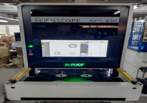
Advanced technologies such as laser drilling and automated optical inspection (AOI) are often employed to ensure precision during drilling, etching, and testing processes. CNC machines are also used for high-accuracy shaping and cutting.
Common Challenges and Solutions During Manufacturing
Heat Management: One of the primary challenges in manufacturing copper core PCBs is maintaining proper heat balance during lamination and soldering processes. Excessive heat can lead to warping or delamination. Manufacturers mitigate this by using precise temperature control and high-quality lamination materials.
Copper Thickness: Handling thicker copper cores is more challenging than working with standard PCBs. The increased weight and density of copper require specialized equipment for drilling, etching, and plating. Using CNC machinery with high torque and precision helps manage these challenges.
Adhesion Issues: Achieving strong adhesion between the copper core and dielectric layer can be tricky. Any impurities or uneven surfaces can result in poor bonding. Thorough surface cleaning and using high-quality laminates ensure a more reliable bond.
Etching Precision: Etching thicker copper layers can sometimes result in uneven traces or over-etching. To address this, manufacturers use advanced chemical processes and real-time monitoring to control the etching process.
In conclusion, the copper core PCB manufacturing process involves advanced techniques and materials that help create highly durable and efficient boards. Despite the challenges, manufacturers have developed solutions that enable the production of copper core PCBs with precise performance for demanding applications.
Chapter 6
Copper Core PCB Design Considerations
Designing Copper Core PCBs requires careful planning and adherence to specific design rules to maximize their thermal and electrical advantages. Below are some key design considerations, best practices, and tips for ensuring optimal performance in copper core PCB designs.
Specific Design Rules and Best Practices
1. Thickness of the Copper Core
The thickness of the copper core plays a critical role in the thermal performance and structural integrity of the PCB. Designers must select the appropriate copper thickness based on the power requirements and the heat dissipation needs of the application. Common copper core thicknesses range from 1.0mm to 3.0mm, but the ideal choice depends on the expected thermal load and mechanical constraints.
2. Dielectric Material Selection
Choosing the right dielectric material between the copper core and the conductive layers is crucial for balancing thermal conductivity and electrical insulation. Materials with high thermal conductivity, such as thermally conductive epoxy or ceramic-filled compounds, should be used to ensure efficient heat transfer. The dielectric material must also maintain excellent electrical insulation properties to prevent short circuits.
3. Via and Plating Design
For optimal heat dissipation and electrical performance, the design of vias (through-holes) must allow for effective thermal transfer from the surface to the copper core. Designers often use thermally conductive vias, which are plated with copper to channel heat away from hot components. It’s important to properly space the vias and ensure that the via walls are fully plated to enhance reliability and reduce resistance.
4. Component Placement
High-power components, such as power transistors or LEDs, should be placed as close as possible to the copper core to maximize thermal dissipation. Proper placement of these components ensures that heat is efficiently transferred to the copper core, preventing localized hotspots that could affect performance. Additionally, sensitive components should be strategically placed to avoid areas of high thermal stress.
Handling Thermal Management and Power Distribution
1. Effective Heat Sinking
Copper core PCBs are used primarily for their superior heat dissipation properties. To make the most of this, designers should consider using large copper areas, thick copper planes, and heat sinks attached directly to the copper core. By maximizing the surface area in contact with the copper core, more heat can be distributed evenly, reducing the risk of overheating high-power components.
2. Power Distribution Layers
Power distribution is another critical aspect of copper core PCB design. To minimize voltage drop and ensure consistent power delivery, designers should use wide traces and thick copper layers for power and ground planes. These layers help distribute current efficiently across the board and reduce impedance, which is particularly important in high-current applications.
3. Thermal Simulation
Thermal simulation software can be used during the design phase to predict how heat will flow through the PCB and where potential hot spots may develop. By simulating various heat loads and component placements, designers can make adjustments before manufacturing to ensure optimal thermal performance. This step is especially important in high-power designs where failure to manage heat properly can lead to premature component failure.
Tips for Ensuring Optimal Performance in Designs
Design for Manufacturability (DFM): When designing a copper core PCB, always ensure that the design complies with the manufacturer’s capabilities. Thick copper cores can be challenging to fabricate, so working closely with your PCB manufacturer to understand their design constraints is essential for successful production.
Minimize Trace Lengths: Shorter trace lengths between high-power components reduce resistance and improve the overall electrical performance of the PCB. Additionally, minimizing the distance between heat-sensitive components and the copper core enhances heat dissipation.
Use Thermal Pads: For components that generate significant heat, using thermal pads connected to the copper core through thermal vias can greatly improve heat transfer. These pads help dissipate heat directly from the component to the copper core, maintaining a cooler operating environment.
Component Shielding: For applications with high-frequency signals, designers may need to implement shielding techniques to prevent electromagnetic interference (EMI). The copper core can also serve as a natural shield against EMI, provided the design incorporates proper grounding and isolation techniques.
Layer Stacking: When designing a multi-layer copper core PCB, the arrangement of layers should consider both thermal and electrical factors. Power and ground layers should be positioned close to the copper core to take advantage of its heat-sinking properties, while signal layers should be isolated to avoid interference.
In summary, designing Copper Core PCBs requires attention to thermal management, power distribution, and manufacturability. By following these design rules and best practices, designers can create efficient, reliable copper core PCBs that perform optimally in high-power and high-temperature environments.
Chapter 7

Copper Core PCB vs. Aluminum Core PCB
Copper Core PCBs and Aluminum Core PCBs are both widely used in applications requiring excellent thermal management and durability. However, they differ significantly in terms of material properties, performance, and costs. Understanding these differences can help you choose the right PCB for your specific application.
Pros and Cons of Each Material
Copper Core PCB
Pros:
- Superior Thermal Conductivity: Copper has a higher thermal conductivity (around 400 W/mK) compared to aluminum (205 W/mK), making Copper Core PCBs more efficient at dissipating heat.
- Better Electrical Conductivity: Copper’s electrical conductivity is also much higher, reducing electrical resistance and improving power distribution in high-frequency and high-current applications.
- Durability: Copper is more robust and can handle higher loads and thermal stress without deforming or losing performance.
Cons:
- Cost: Copper is significantly more expensive than aluminum, which makes Copper Core PCBs costlier to produce. This higher cost may not be justified in low-power applications where aluminum provides sufficient performance.
- Weight: Copper is denser and heavier than aluminum, which can be a drawback in weight-sensitive applications such as aerospace and portable electronics.
Aluminum Core PCB
Pros:
- Lower Cost: Aluminum is more affordable than copper, which makes Aluminum Core PCBs a cost-effective option for a wide range of applications, particularly in consumer electronics and LED lighting.
- Lightweight: Aluminum is lighter than copper, making it a preferred choice in industries where weight is a critical factor, such as in automotive and aerospace applications.
- Sufficient Thermal Management: While aluminum’s thermal conductivity is lower than copper, it is still far superior to traditional FR-4 substrates, making Aluminum Core PCBs suitable for many heat-sensitive applications like LED lights.
Cons:
- Lower Thermal Conductivity: Although aluminum has decent heat dissipation properties, it cannot match the performance of copper in high-power applications.
- Electrical Conductivity: Aluminum’s electrical conductivity is lower than copper, making it less ideal for high-frequency circuits or applications that require efficient power distribution.
- Less Durable: Aluminum is less durable under extreme thermal and mechanical stress compared to copper, which can limit its use in high-power, high-precision applications.
Cost, Performance, and Application Suitability
Cost:
Aluminum Core PCBs are generally more cost-effective, making them suitable for budget-conscious projects or applications where thermal performance is important but not critical. Copper Core PCBs, on the other hand, are more expensive due to the higher cost of copper but provide better performance in terms of both thermal and electrical conductivity.
Performance:
When it comes to performance, Copper Core PCBs offer superior heat dissipation, better electrical conductivity, and greater durability. This makes them the go-to choice for high-power applications, such as power converters, automotive electronics, and high-performance LED systems. Aluminum Core PCBs are suitable for applications that require good heat management but don’t need the high-end thermal or electrical performance that copper provides. Examples include consumer electronics, LED lighting, and some automotive systems.
Application Suitability:
- Copper Core PCBs: Best suited for high-power applications where extreme heat dissipation and electrical performance are crucial, such as high-current circuits, power devices, automotive electronics, and industrial machinery.
- Aluminum Core PCBs: Ideal for mid-range applications where cost and weight are important considerations, such as LED lighting, consumer electronics, and automotive interior systems.
When to Choose Copper Over Aluminum and Vice Versa
Choose Copper Core PCBs when:
- Your application requires superior heat dissipation, such as in high-power LED lighting, automotive electronics, or power supplies.
- You need high electrical conductivity for high-frequency or high-current circuits, ensuring minimal energy loss.
- Durability and long-term performance are critical, especially in harsh environments where components are subjected to thermal cycling and high stress.
Choose Aluminum Core PCBs when:
- Cost is a key consideration, and the application does not require the extreme heat dissipation and electrical performance that copper provides.
- Weight is a concern, and you need a lighter PCB for portability or to reduce the overall weight of the device, as in automotive and aerospace industries.
- The application involves medium-power or heat-sensitive electronics, such as consumer electronics or low-to-mid-power LED systems.
In summary, Copper Core PCBs excel in high-performance, high-power environments where thermal management and electrical efficiency are critical. Aluminum Core PCBs, while less capable in these areas, offer a cost-effective and lightweight solution for applications that do not require the extreme performance characteristics of copper. Choosing between copper and aluminum depends on the specific needs of your project in terms of cost, performance, and application requirements.
Chapter 8
How to Test copper core PCBs?
Testing Copper Core PCBs is crucial to ensure that they meet the desired performance standards, particularly in terms of thermal management, electrical performance, and durability. Below are some of the key methods and processes for testing Copper Core PCBs.
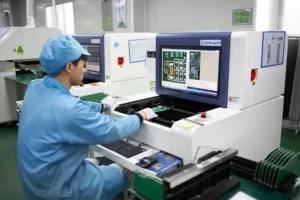
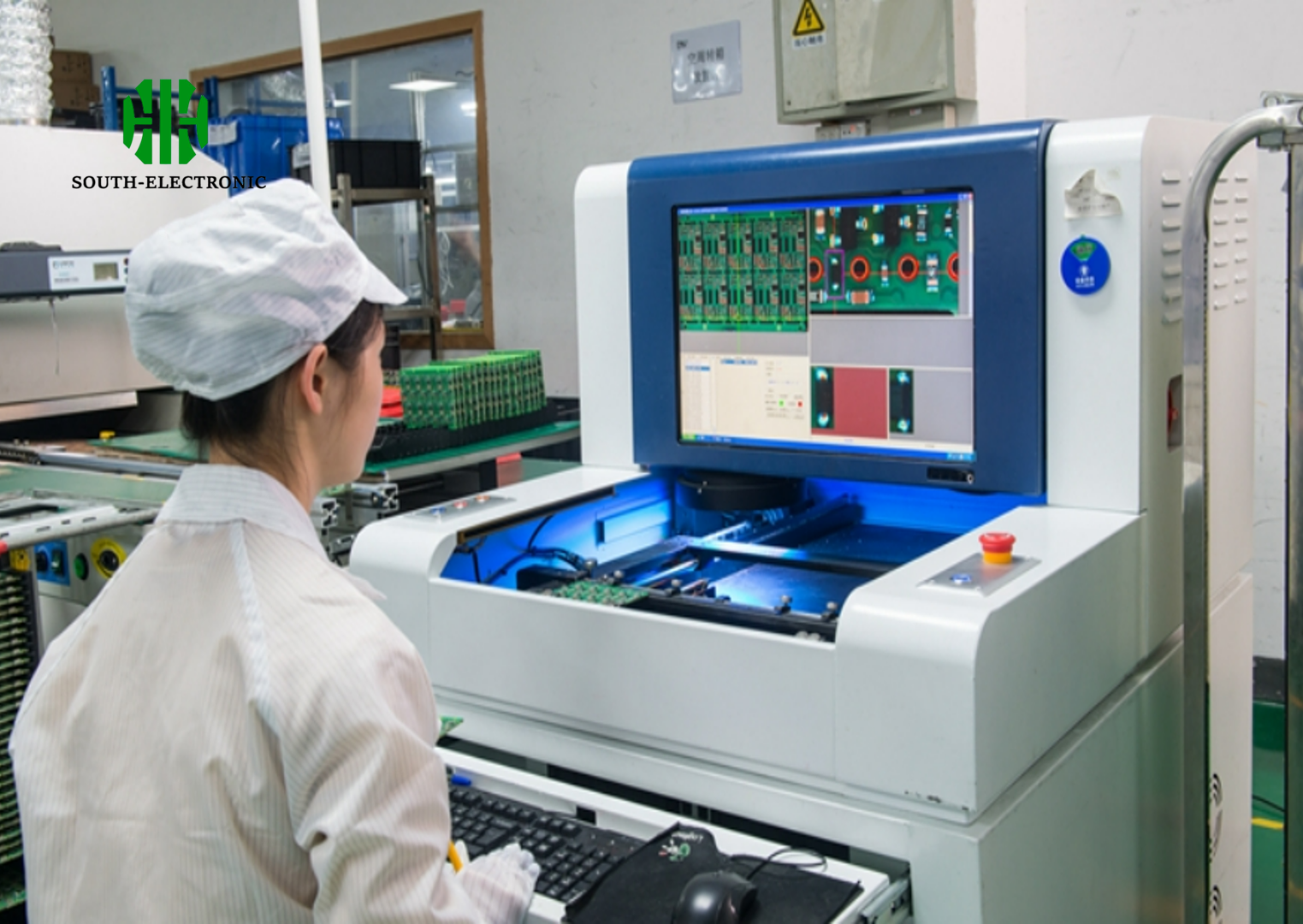
1. Visual Inspection
The first step in testing Copper Core PCBs involves a thorough visual inspection to identify any physical defects such as misaligned layers, incomplete etching, or issues with vias and traces. This process is often done manually or with Automated Optical Inspection (AOI) systems to detect issues that may affect performance.
- What to Look For:
- Misaligned copper layers.
- Incomplete or uneven etching of traces.
- Surface defects such as scratches or cracks.
- Inconsistent solder mask application.
2. Thermal Conductivity Test
Since thermal management is a key feature of Copper Core PCBs, testing the thermal conductivity is essential to verify how efficiently the board can dissipate heat. This test is performed using specialized equipment that measures the heat transfer from high-power components to the copper core.
How It Works:
A thermal sensor is placed on the PCB to monitor heat distribution as the board is subjected to power loads. The effectiveness of the copper core’s heat dissipation is assessed by measuring the rate at which heat is transferred away from hot spots.Key Metrics:
- Heat transfer rate.
- Temperature distribution across the PCB surface.
- Maximum temperature reached during operation.
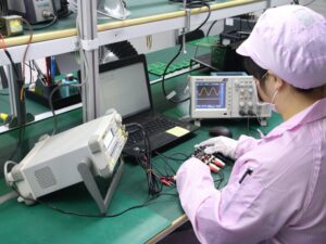
3. Electrical Conductivity Test
Copper Core PCBs are known for their excellent electrical conductivity. Testing for electrical performance ensures that the copper traces and core can handle the required current loads without excessive resistance, which can cause overheating or power losses.
Test Methods:
- Conductivity Measurement: A multi-meter or specialized equipment is used to measure the resistance across the copper traces and vias.
- Current Handling Test: The PCB is subjected to high current loads, and its ability to handle these loads without performance degradation is measured.
Key Metrics:
- Resistance across traces and vias.
- Voltage drops and power losses under load.
- Integrity of electrical connections (especially at via points).
4. Heat Cycle and Stress Testing
Heat cycling is important to ensure that Copper Core PCBs can withstand the repeated expansion and contraction caused by temperature fluctuations in real-world applications. Stress testing simulates extreme operational conditions to verify the board’s resilience and durability.
How It Works:
The PCB is subjected to a series of temperature cycles, alternating between high and low temperatures. This process identifies any issues with material expansion, delamination, or mechanical failure due to thermal stress.Key Metrics:
- Thermal expansion rates.
- Resistance to delamination or cracking.
- Performance under repeated thermal cycling.
5. Functional Testing
Functional testing ensures that the PCB works as intended in its final application. This includes powering the board and running it through typical operational conditions, such as those found in automotive electronics, LED lighting, or power supply units.
Test Setup:
The PCB is connected to a test rig where it operates under simulated real-world conditions. Sensors measure its performance, including electrical signal integrity, power distribution, and thermal behavior.Key Metrics:
- Signal integrity and noise levels.
- Voltage and current stability under load.
- Operational temperatures under typical use conditions.
6. High-Power Load Testing
For Copper Core PCBs designed for high-power applications, such as power converters or automotive systems, high-power load testing is essential. This test checks the board’s ability to handle large electrical loads without overheating or experiencing electrical failures.
Test Setup:
The PCB is subjected to maximum current loads while thermal and electrical sensors monitor its performance. The goal is to ensure that the board can handle high power without suffering from heat buildup, voltage drops, or component failure.Key Metrics:
- Maximum current load capacity.
- Thermal stability at peak power.
- Integrity of the board and components under high-stress conditions.
7. Solderability Test
Solderability tests are conducted to ensure that the surface of the PCB allows for proper soldering of components, which is essential for reliable connections in assembly. These tests are especially important for Copper Core PCBs, where heat dissipation could affect soldering quality.
How It Works:
The PCB is exposed to soldering temperatures, and the quality of the solder joints is evaluated. This test ensures that the copper surface allows for proper wetting, and that there are no defects such as cold solder joints or poor adhesion.Key Metrics:
- Solder joint strength.
- Wetting properties of the copper surface.
- Absence of soldering defects.
8. Reliability Testing
To verify long-term durability and reliability, Copper Core PCBs undergo environmental and reliability testing. These tests simulate harsh operational conditions, including humidity, vibration, and corrosive environments, to ensure that the PCB can endure long-term use without failure.
Tests Include:
- Humidity Testing: The board is exposed to high levels of humidity to assess its resistance to moisture ingress and corrosion.
- Vibration Testing: Mechanical vibration is applied to evaluate the structural integrity of the PCB under motion, which is critical for automotive and industrial applications.
- Salt Spray Testing: To assess the corrosion resistance of the PCB in marine or outdoor applications.
Key Metrics:
- Corrosion resistance.
- Structural integrity under vibration.
- Moisture resistance.
In summary, testing Copper Core PCBs involves a combination of thermal, electrical, mechanical, and environmental tests to ensure the board meets performance and reliability standards. Thorough testing is crucial for verifying that Copper Core PCBs can perform optimally in demanding applications where heat dissipation and electrical efficiency are essential.
Chapter 9
How to Choose the Right Copper Core PCB Supplier?
Choosing the right Copper Core PCB supplier is a critical decision that can impact the quality, performance, and reliability of your final product. Below are key factors to consider when selecting a supplier to ensure that they meet your technical and business requirements.
1. Experience and Expertise
A supplier with extensive experience in manufacturing Copper Core PCBs will have the knowledge and technical expertise to handle the complexities involved in producing high-quality boards. Look for suppliers that specialize in copper core technology and have a proven track record of delivering PCBs for high-performance applications like automotive electronics, power supplies, or LED lighting.
- Questions to Ask:
- How many years of experience do they have in producing Copper Core PCBs?
- Do they have specific expertise in your industry or application?
2. Quality Standards and Certifications
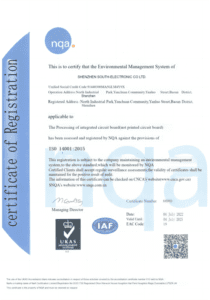
Quality is paramount when it comes to Copper Core PCBs, especially for high-power or heat-sensitive applications. Ensure that the supplier adheres to international quality standards, such as ISO 9001 for quality management and IPC standards for PCB manufacturing.
- Certifications to Look For:
- ISO 9001: Quality Management System certification.
- IPC Standards: IPC-6012 (Qualification and Performance Specification for Rigid PCBs) and IPC-A-600 (Acceptability of Printed Boards).
- UL Certification: Ensures that the PCBs meet safety standards for electrical products.
3. Manufacturing Capabilities
Assess the supplier’s manufacturing capabilities to ensure they can handle the specific requirements of your Copper Core PCB project. This includes the ability to work with thick copper cores, specialized laminates, and high-precision production equipment.
- Key Manufacturing Considerations:
- Maximum copper thickness they can handle.
- Advanced lamination techniques for dielectric materials.
- CNC machining capabilities for precise drilling and routing.
- High-end plating technologies for vias and through-holes.
4. Testing and Quality Control
A reliable Copper Core PCB supplier will have stringent testing and quality control measures in place. This includes in-process inspections and end-product testing to ensure the board meets the required thermal, electrical, and mechanical specifications.
- Testing Methods to Expect:
- Automated Optical Inspection (AOI) to check for defects in copper traces.
- Thermal conductivity tests to ensure efficient heat dissipation.
- Electrical testing for conductivity, current handling, and signal integrity.
- Environmental stress testing, such as thermal cycling and vibration tests.
5. Customization and Flexibility
Your project may have unique design or production requirements. The ideal supplier should offer customization options for copper thickness, board dimensions, layer count, and dielectric materials. Flexibility in production processes allows for tailoring the PCB to your specific needs.
- Customization Options to Consider:
- Custom copper core thicknesses based on heat dissipation needs.
- Flexible production runs (low to high volumes).
- Choice of surface finishes (e.g., ENIG, OSP, or HASL) for optimal solderability.
- Specialized dielectric materials for enhanced performance.
6. Production Capacity and Lead Time
The supplier’s production capacity is another important consideration, especially if you need to scale production or meet tight deadlines. A supplier with high-volume production capabilities and efficient lead times can help you manage project timelines and avoid delays.
- What to Assess:
- Production line capabilities and capacity.
- Average lead time for prototype and mass production.
- On-time delivery performance (check reviews or case studies).
7. Technical Support and Communication
Reliable communication and technical support are essential, especially when working with complex designs like Copper Core PCBs. Choose a supplier that provides dedicated technical support to assist with design, production, and troubleshooting issues.
- Questions to Ask:
- Do they offer design consultation and DFM (Design for Manufacturability) feedback?
- How responsive is their technical support team?
- Do they offer real-time updates on production progress?
8. Pricing and Cost Transparency
While cost should not be the sole deciding factor, it’s important to find a supplier that offers competitive pricing without compromising quality. Transparent pricing helps you understand what is included in the costs, such as materials, testing, and shipping.
- What to Look For in Pricing:
- Clear breakdown of costs (materials, labor, testing, etc.).
- Any hidden fees or additional charges.
- Flexibility in pricing for different volumes (prototypes vs. mass production).
9. Reputation and Customer Reviews
Look into the supplier’s reputation in the industry by reviewing customer testimonials, case studies, and ratings. A supplier with consistently positive feedback is likely to deliver quality products and excellent service.
- Where to Check:
- Online reviews on platforms like Google or Alibaba.
- Case studies or references from similar companies in your industry.
- Industry awards or recognition for quality and performance.
10. Global Shipping and Logistics
If you are sourcing from an international supplier, ensure they have a reliable shipping and logistics network. Delays in shipping or issues with customs can affect your project timeline.
- Logistics to Consider:
- Global shipping options and lead times.
- Experience with customs clearance and documentation.
- Shipping costs and options (air, sea, or express delivery).
Conclusion
Selecting the right Copper Core PCB supplier involves evaluating their expertise, quality standards, production capabilities, and reliability. By considering factors like certifications, customization options, technical support, and cost transparency, you can choose a supplier that meets your project’s needs and delivers high-quality Copper Core PCBs on time. Be sure to conduct thorough research, check customer reviews, and communicate directly with potential suppliers to make an informed decision.
Chapter 10
Future Trends in Copper Core PCBs
Increased Demand for High-Power Applications: As devices become more powerful and compact, the demand for copper core PCBs that can efficiently manage heat will rise. This is particularly relevant for applications in electric vehicles, aerospace, and telecommunications.
Advancements in Thermal Management: Future copper core PCBs will likely incorporate advanced thermal management technologies. These innovations could involve new materials and architecture designs to further improve heat dissipation.
Miniaturization and Precision: As the industry continues to push towards smaller and more efficient devices, there will be a trend towards the development of smaller, more precise copper core PCBs. This requires advancements in manufacturing technologies to maintain performance while reducing size.
Integration with Flexible Electronics: Copper core PCBs might increasingly be integrated with flexible electronics, offering durability and flexibility in design. This trend is important for wearable technology and flexible displays.
Eco-friendly Manufacturing Processes: With a growing focus on sustainability, there will be a push towards more environmentally friendly manufacturing processes. This includes reducing waste, recycling, and using eco-friendly materials in the production of copper core PCBs.
Enhanced Electrical Performance: Future copper core PCBs will focus on improving electrical performance, supporting higher data rates and better signal integrity, crucial for modern high-speed electronics.
Cost Reduction Strategies: As demand increases, there will be an emphasis on developing cost-effective manufacturing processes that maintain quality and performance, making copper core PCBs more accessible for various applications.
These trends reflect the ongoing innovation and adaptation within the electronics industry to meet the growing demands for efficiency, sustainability, and performance in modern devices.
Get in touch
Where Are We?
Industrial Park, No. 438 Donghuan Road, No. 438, Shajing Donghuan Road, Bao'an District, Shenzhen, Guangdong, China
Floor 4, Zhihui Creative Building, No.2005 Xihuan Road, Shajing, Baoan District, Shenzhen, China
ROOM A1-13,FLOOR 3,YEE LIM INDUSTRIAL CENTRE 2-28 KWAI LOK STREET, KWAI CHUNG HK
service@southelectronicpcb.com
Phone : +86 400 878 3488
Send us a message
The more detailed you fill out, the faster we can move to the next step.

-
Flexibility in Ordering:
Enjoy the flexibility of ordering from MOQ 1pc, tailored to your specific automotive needs.
-
Experienced Team:
Benefit from the expertise of our team, each with significant experience in the automotive PCB industry.
-
Competitive Pricing:
As the primary manufacturer, we offer the best prices and quality compared to other suppliers.
-
Comprehensive Service:
Our wide range of processing equipment ensures total satisfaction within the automotive industry.
-
Fast Delivery:
With our optimized production line and continuous operation, we ensure rapid turnaround times for your orders.
-
Guaranteed Satisfaction:
We are an ISO9001 certified factory, dedicated to quality and clear communication to enhance your experience with us.

