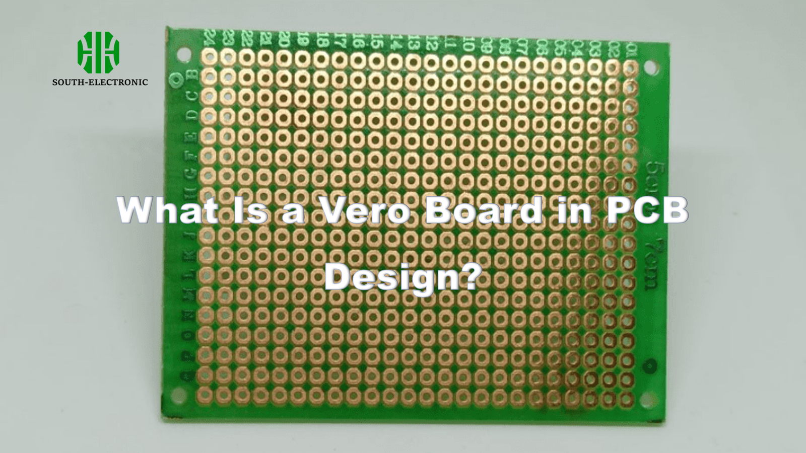
Struggling to turn your breadboard prototype into something permanent? Vero boards[^1] solve the "in-between" stage of electronics projects. This humble tool bridges temporary testing and professional PCB manufacturing.
A Vero board (stripboard) is a solderable prototyping board[^2] with pre-drilled holes and copper strips[^3]. It creates semi-permanent circuits for testing and low-volume production, offering durability and cost-effectiveness between breadboards and custom PCBs.
Whether you’re building your first circuit or scaling prototypes, understanding Vero boards unlocks faster project development. Let’s explore their uses, comparisons, and best practices.
What Exactly is a Vero Board and How Does it Work in Prototyping?
Hate rebuilding circuits after breadboard testing? Vero boards turn messy wire nests into organized layouts. The secret lies in their simple grid design.
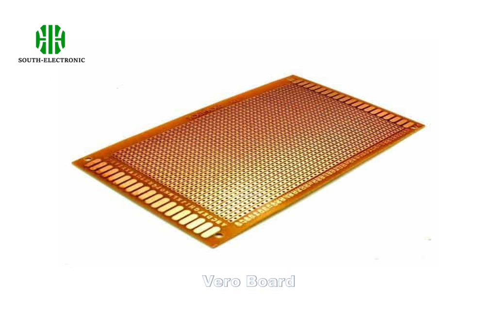
Vero boards feature parallel copper strips connecting columns of 0.1" spaced holes. Users create circuits by soldering components and cutting specific strips to prevent short circuits, enabling customizable yet stable prototype construction.
)
Three Key Functional Elements
-
Copper Grid System
Continuous strips allow multiple component connections without wires.
Example: Connecting seven LEDs to a common ground strip -
Breakable Connections
Use a drill bit or utility knife to isolate circuit sections.
Common mistake: Cutting both sides of the strip (weakens board) -
Component Placement
Follows standard 0.1" spacing compatible with most DIP components
| Feature | Breadboard | Vero Board |
|---|---|---|
| Connection Method | Spring clips | Soldered joints |
| Reusability | High | Moderate |
| Current Capacity | Low (20MHz clocks) |
Vero Board vs Breadboard vs PCB: Which Should You Choose for Your Project?
Choosing prototyping tools feels like picking between speed, cost, and durability. Each platform serves different development stages.
Use breadboards[^4] for initial testing, Vero boards for functional prototypes needing durability, and custom PCBs[^5] for final production. Vero boards excel in projects requiring moderate modifications and physical robustness.
)
Decision Factors Explained
1. Project Stage
- Concept phase → Breadboard (quick changes)
- Validation phase → Vero board (reliable testing)
- Mass production → PCB (cost efficiency)
2. Budget Constraints - Breadboard: $5-$20
- Vero board: $2-$10 per unit
- Custom PCB: $50+ (minimum order quantities)
3. Skill Level - Absolute beginners start with breadboards
- Intermediate users benefit most from Vero boards
Personal story: I once burned three microcontroller chips on a breadboard due to loose connections – switched to Vero boards for sensor array projects.
What Are the Key Advantages and Limitations of Using Vero Boards?
Vero boards shine in specific scenarios but can frustrate complex designs. Know when to push their limits and when to switch to PCBs.
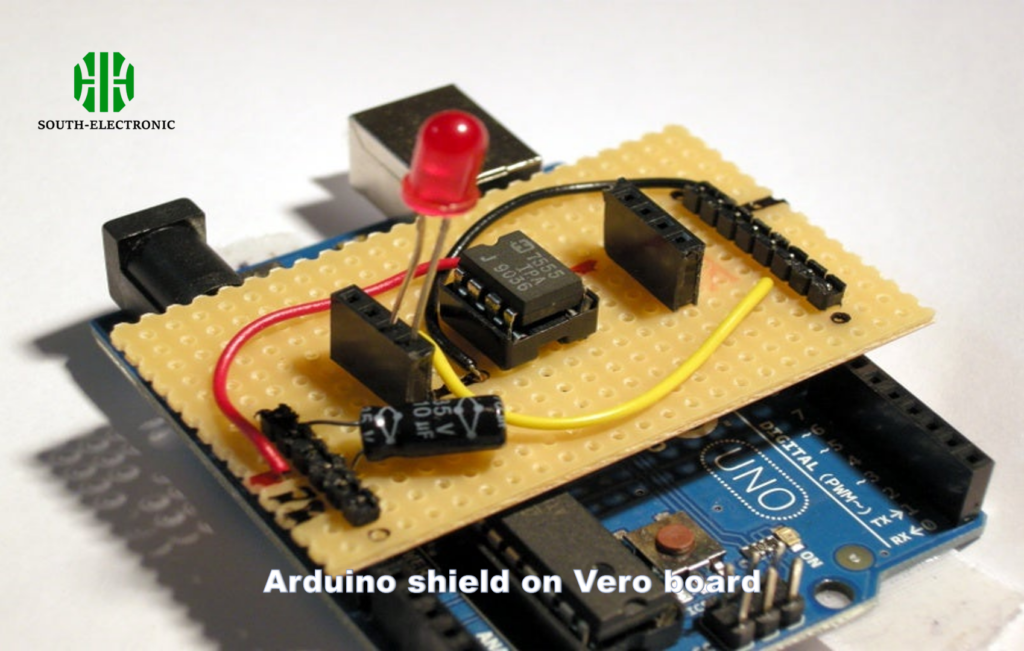
Advantages include low cost, quick assembly, and component density. Limitations involve fixed layouts, time-consuming modifications, and limited high-frequency performance. Best for analog circuits and digital projects below 20MHz.
)
Performance Considerations
- Thermal Management
Copper strips dissipate heat better than breadboards
But – No thermal relief pads (risk of lifted pads) - Signal Integrity
Acceptable for:- DC power circuits
- Audio frequency ranges
Avoid for: - RF designs
- High-speed digital (>20MHz clocks)
- Mechanical Stress
Pros: Withstands vibration better than breadboards
Cons: Repeated soldering weakens pads
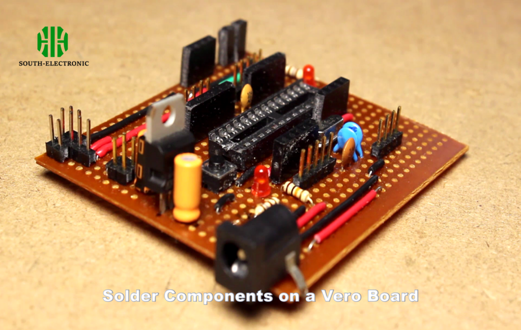
How to Properly Solder Components on a Vero Board: Step-by-Step Guide
Poor soldering ruins even the best designs. Follow this battle-tested technique for reliable joints.
**1. Insert and bend component legs at 45° to secure parts
- Apply iron to pad + lead for 2 seconds
- Feed solder into heated joint – not the iron tip
- Inspect for concave "volcano" shape – no blobs or gaps**
)
Troubleshooting Common Issues
Cold Joints (Dull/Gray)
- Cause: Insufficient heat
- Fix: Reheat until shiny
Bridging Between Pads
- Cause: Excess solder
- Fix: Use solder wick
Lifted Pads
- Cause: Overheated pads
- Prevention: Limit iron contact to 3 seconds
Personal hack: Colored sharpies mark planned trace cuts before soldering – avoids confusion.
What Are Common Design Mistakes to Avoid with Vero Boards?
Even experienced makers make these errors. Learn from others’ burned fingers and blown components.
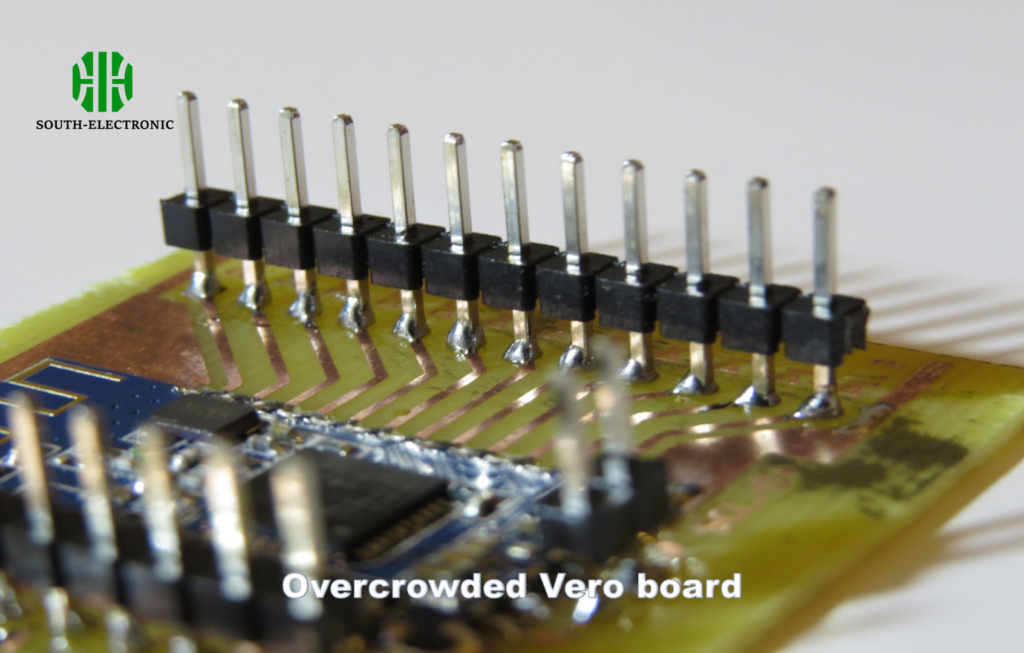
Top mistakes include forgetting trace cuts, overcrowding components, and ignoring power distribution[^6]. Planning with grid paper and testing sections prevents most issues.
)
Prevention Checklist
-
Layout Planning
- Sketch connections first
- Mark required trace cuts
-
Power Distribution
- Dedicate entire strips to VCC/GND
- Add decoupling caps near ICs
-
Signal Routing
- Keep high-current paths short
- Avoid crossing uncut strips
| Mistake | Consequence | Solution |
|---|---|---|
| Uncut adjacent strips | Short circuits | Verify cuts with multimeter |
| No component spacing | Overheating | Follow datasheet distances |
| Mixed analog/digital | Noise coupling | Separate supply strips |
Conclusion
Vero boards remain essential for electronics enthusiasts seeking durable prototypes without PCB costs. Mastering their use accelerates project development while teaching fundamental circuit design skills. Plan layouts carefully, solder properly, and know when to upgrade to custom boards.
[^1]: Explore this link to gain a deeper understanding of Vero boards and their significance in electronics prototyping.
[^2]: Learn about solderable prototyping boards and how they can enhance your electronics projects.
[^3]: Discover the role of copper strips in Vero boards and how they facilitate circuit connections effectively.
[^4]: Learn about breadboards and their role in rapid prototyping, making them ideal for beginners and quick tests.
[^5]: Discover how custom PCBs can optimize your designs for mass production, ensuring efficiency and reliability.
[^6]: Understanding power distribution is crucial for circuit stability; this resource will guide you in optimizing your designs.

