
Ever faced unpredictable circuit failures? Loose copper layers or signal distortions plague PCBs. PCB laminates solve these woes by bonding layers into reliable units.
PCB laminates fuse copper, prepreg, and core materials under heat/pressure to form your board’s backbone. They provide mechanical support and electrical insulation. Common types include FR-4 for general use or specialized options like PTFE for high-frequency needs.
Understanding materials isn’t enough though. How you apply them defines your PCB’s success. Let’s tackle critical usage decisions designers face.
When to upgrade from FR-4 to specialty PCB laminates?
Stubborn signal loss ruins FR-4 boards? Heat degradation causes erratic behavior? High-stress environments demand tougher laminates.
Switch when encountering GHz frequencies exceeding FR-4’s bandwidth, extreme temperatures above 130°C, or critical signal integrity needs. Specialty PCB laminates outperform FR-4 but increase cost 5-10x.
Balancing Performance Factors
Specialty alternatives shine where FR-4 fails – but choose thoughtfully. I evaluate three key parameters:
Frequency Response
FR-4 struggles above 1GHz due to dielectric inconsistency. For microwave/RF boards, polyimide laminates maintain stable Dk values. Rogers materials further minimize signal loss even at 40GHz.
Thermal Endurance
Continuous thermal cycling cracks FR-4 below its 130-140°C Tg limit. Polyimide handles 220°C+, while ceramic-filled laminates tolerate 300°C intermittent spikes. These prevent warping in industrial motors.
Cost-Benefit Tradeoffs
| Material | Cost Factor | Ideal Use Case |
|---|---|---|
| FR-4 | 1x | Consumer devices 10GHz systems like satellite transmitters. Its ultra-low loss tangent preserves signals that FR-4 dissipates or distorts, despite 8-12x cost premiums.** |
PTFE’s High-Frequency Advantages
This fluoropolymer beats alternatives in RF-critical domains:
Signal Integrity
PTFE’s 0.001-0.005 loss tangent leaps ahead of FR-4’s 0.02. Combined with stable Dk (±0.02 tolerance), it ensures millimeter-wave signals transmit cleanly.
Thermal Management
PTFE efficiently distributes localized heat from RF amplifiers. In my antenna projects, PTFE substrates consistently lowered hotspots by 8-12°C versus ceramic options.
Manufacturing Rewards
PTFE laminates support tighter impedance tolerances (±3%), essential for impedance-sensitive microwave filters and multilayer RF boards. Matching copper coefficients prevents temperature-induced delamination.
The caveat? PTFE drills poorly, requiring specialized tooling and plating. Reserve it for documented GHz requirements.
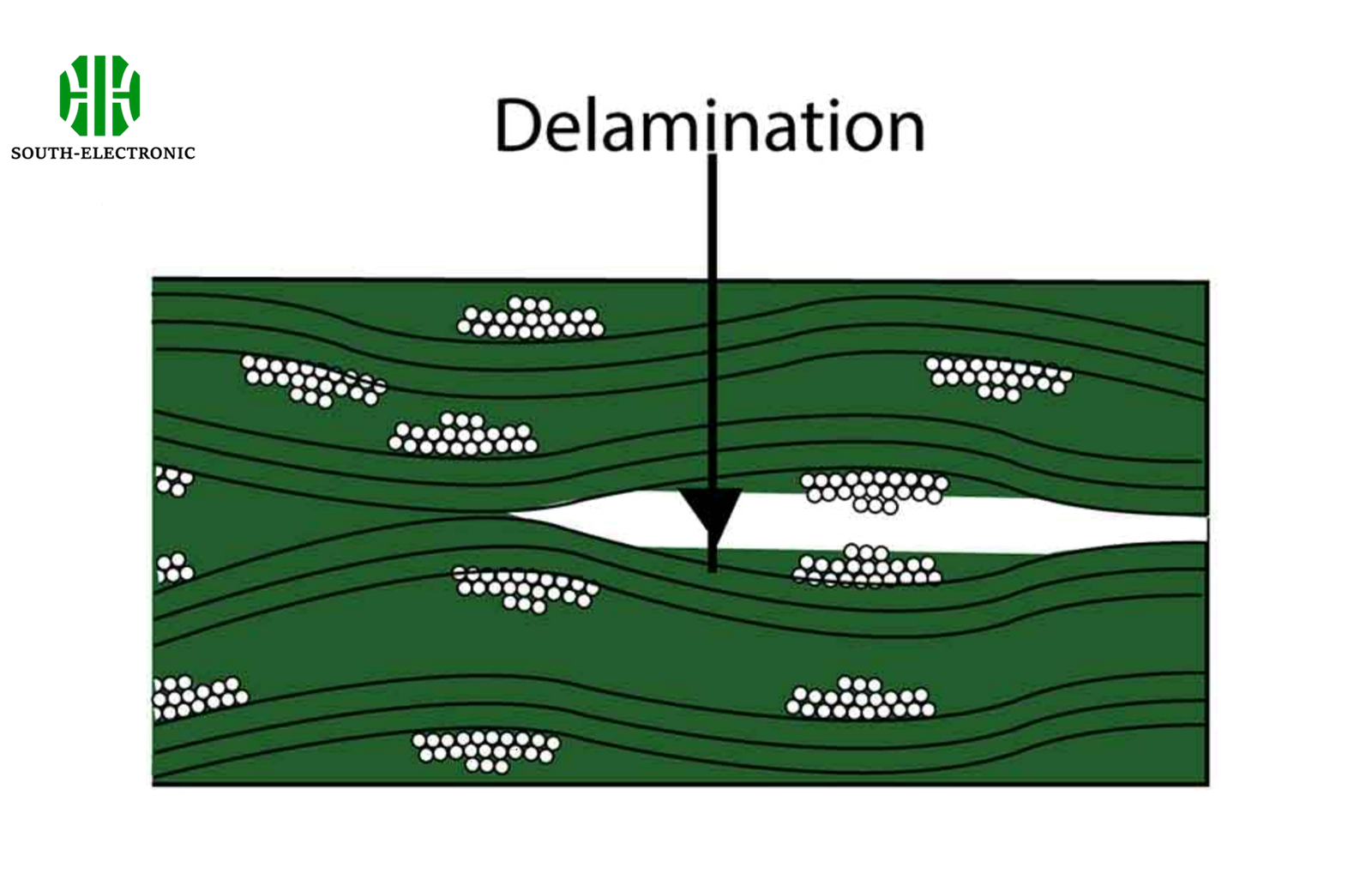
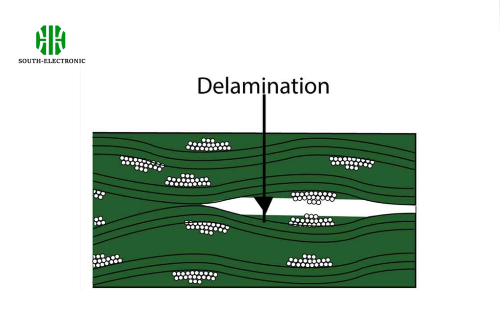
How to prevent PCB delamination via material and design?
Witnessed bubbling layers after reflow? Delamination kills boards post-assembly. Heat/moisture attack weak bonds, causing irreparable layer separation. Proper choices create bulletproof bonds.
Prevent delamination by selecting high-Tg materials (>170°C), controlling moisture (<0.2% weight gain), and balancing copper distributions. Also optimize stack-up symmetry and adhesion processes during lamination.
Multi-Defense Strategy
Address all risk vectors for reliable layering:
Material Preparation
Dry prepreg storage (<5% humidity) prevents vapor explosions during soldering. I precondition laminates at 130°C for 4 hours pre-fabrication. Verify CTE values align between layers to avoid thermal stress cracks.
Stack-Up Protocols
| Imbalance Risk | Solution | Benefit |
|---|---|---|
| Asymmetric copper | +/-5% thickness variance | Prevents warp from uneven stress |
| Adjacent prepreg layers | Press-outs <50% resin content | Eliminates void formation |
| Temperature shocks | Progressive oven ramps | Lowers thermal strain rate by 60% |
Process Controls
Pressure dwell times must exceed resin cure minima. In my factory audits, increasing 200°C press dwell from 90 to 120 minutes reduced delamination by 75%. Post-lamination bake stabilizes interlayer adhesion.
Conclusion
PCB laminates form your board's core structure. Use FR-4 economically, upgrade for extremes, target PTFE at GHz frequencies, and combat delamination through holistic design precautions.

