
Struggling with unreliable PCB connections? Constant disconnects ruin device performance and frustrate users. Discover the resilient solution solving this headache.
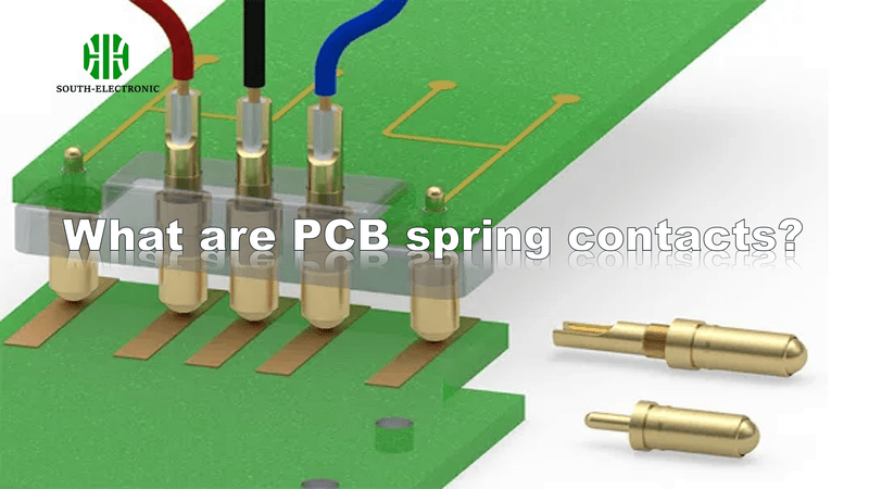
PCB spring contacts are spring-loaded components creating secure electrical connections on circuit boards. They use internal springs to maintain constant pressure against mating surfaces, ensuring stable low-resistance contact in demanding conditions like vibration or temperature shifts.
Finding the right contact type prevents future headaches. Let’s compare options before tackling design essentials.
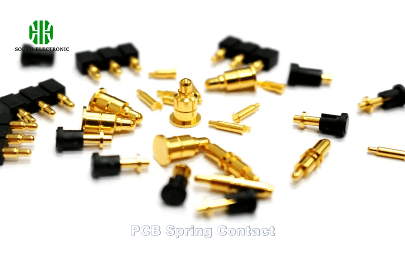
Which fits your PCB needs: pogo pins, spring fingers, or cantilever contacts?
Facing connection failures in your prototypes? Choosing wrong contacts wastes time and money. Match your project’s demands to the optimal solution.
Pogo pins suit vertical compression connections like test points. Spring fingers work for sliding applications like edge connectors. Cantilever contacts handle lateral deflection in battery compartments.
Critical selection factors
Consider these parameters when deciding:
| Current Rating | Lifetime Cycles | Force Required | |
|---|---|---|---|
| Pogo Pins | 1-5A | 10k-100k | Medium |
| Spring Fingers | 3-15A | 500k-1M | Light |
| Cantilevers | 5-30A | 50k-200k | Heavy |
Pogo pins compress vertically like tiny pistons. I use them for temporary test interfaces requiring precise alignment. Their main advantage is space efficiency. But plating wears faster than other types.
Spring fingers slide against surfaces. They shine in card-edge connectors needing low friction. Gold plating lasts longer here because force distributes evenly across contact area. However, dust accumulation affects performance.
Cantilever springs need robust mounting points. They handle high vibration well when anchored correctly. The bending motion absorbs mechanical shock better than pogo pins. But they require careful stress calculations in the PCB layout.
How to design PCB layouts for reliable spring contact connections?
Getting intermittent errors after assembly? Poor layout choices create high resistance points. Follow key guidelines to prevent field failures.
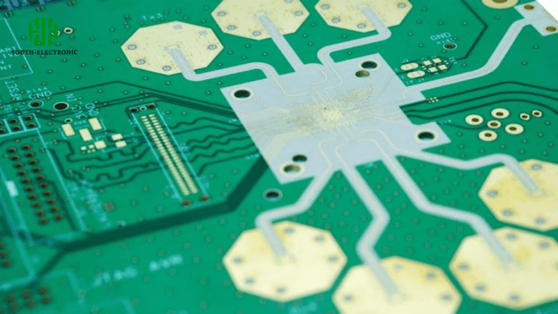
Space pads at least 3mm from board edges. Use oval pads larger than contact points. Position ground springs first near corners to stabilize mating components.
Layout optimization checklist
Implement these critical design rules:
| Priority | Design Rule | Function |
|---|---|---|
| 1 | Keepout zones | Prevents short circuits |
| 2 | Anchor points | Absorbs mechanical stress |
| 3 | Plating thickness | Ensures durability |
| 4 | Solder mask clearance | Avoids interference |
Always define keepout zones around contact areas. I learned this after a failed prototype shorted against components. Position no copper within 1.2mm of pads. Non-conductive zones prevent electrical leakage.
Use auxiliary anchor points near high-force contacts. These anchors absorb mechanical stress that could crack solder joints. Place anchors diagonally opposite mating points. Four anchors usually suffice for standard connections.
Specify ≥2μm hard gold plating where springs touch. Gold plating protects against corrosion better than alternatives. ENIG plating wears too quickly in spring contact applications. Thicker plating extends connector lifecycles considerably.
Why do PCB spring contacts fail?
Seeing intermittent device resets or data errors? Contact failures often disguise themselves as software glitches. Pinpoint these common failure sources.
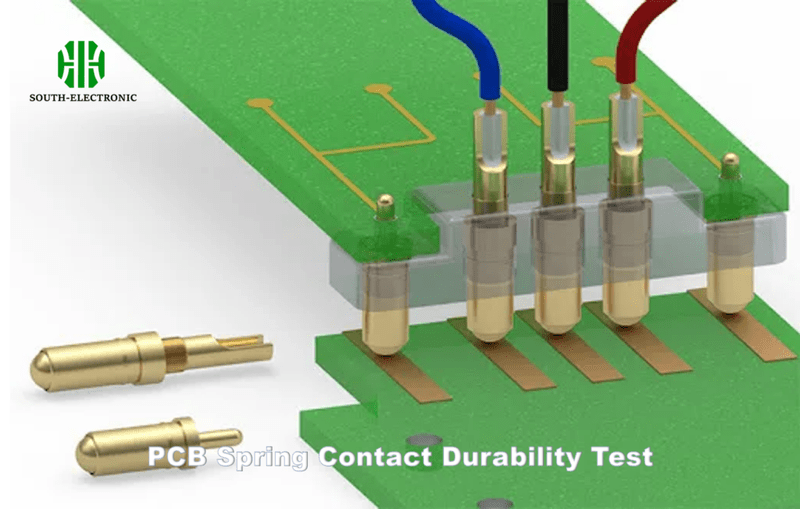
Contaminated contacts cause 70% of intermittent failures. Metal fatigue and plating erosion follow as top culprits. Spring arms lose tension after excessive deflection cycles.
Prevention and remediation
Address root causes with targeted solutions:
| Failure Cause | Solution | Prevention Tip |
|---|---|---|
| Corrosion | Clean with IPA | Use sealed housings |
| Metal Fatigue | Reduce deflection | Control mating angles |
| Plating Wear | Thicker gold | Specify lubricated contacts |
| Contamination | Environmental seals | Add protective caps |
Corrosion begins at microscopic scratches. I recommend sealed connector housings in humid environments. Conformal coating helps but limits repair options. Silicone seals provide good moisture barriers.
Metal fatigue develops differently per contact type. Pogo pins fatigue from over-compression exceeding rated travel. Cantilevers fail from excessive lateral bend angles. Always enforce mechanical limits during assembly.
Plating wears fastest at high friction points. Apply PTFE lubricant during manufacturing for heavy-cycling applications. Self-lubricating coatings add cents per unit but triple contact lifespan.
Conclusion
Choose spring contacts matching your mechanical demands. Design layouts preventing stress and contamination. Understand failure modes ensuring reliable electrical connections long-term.


