

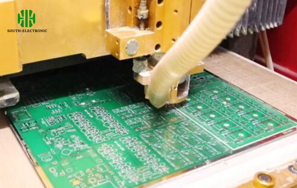
Prototyping PCBs feels frustrating. Costs balloon unexpectedly. Materials waste time. Manual processes drain budgets. Why do prices swing so wildly between prototypes and mass production? Let me explain the key cost drivers.
PCB milling costs shift dramatically from prototypes to production. Prototypes cost more per unit due to material waste, manual setups, and low volumes. Production runs slash costs through efficient material use, automation, and scale. I track three main factors affecting your pricing.
Understanding these differences saves serious money. Whether you’re testing one board or making thousands, recognizing what drives expenses helps you budget smarter. Now explore the tools and materials shaping your milling expenses.
What software, feeds, speeds, and material considerations are needed for flawless PCB milling?
Milling disasters feel exhausting. Wrong feeds ruin boards. Incompatible software wastes hours. Material mistakes cause costly do-overs. Don’t gamble with settings—your entire project hangs in the balance.
Flawless milling requires tuned software and physics. Feed rates adjust for copper thickness. Speeds change with bit size. Material choices alter milling behavior. I prioritize five critical factors for perfect results every time.
Core Software Requirements
Industry software handles design conversions automatically. I use standard tools converting Gerber files to milling paths. These eliminate manual errors. Top programs also simulate cuts before execution. This prevents real-world mistakes. Always verify software compatibility with your machine model.
Material-Specific Settings
Copper thickness demands adjustments. Thin copper needs lighter passes. Fiberglass substrates require different RPM than ceramics. Test speeds on scrap material first. Keep a settings journal for each material type.
| Material Type | Recommended Feed Rate (mm/min) | Spindle Speed (RPM) |
|---|---|---|
| Standard FR4 | 100-150 | 60,000-80,000 |
| Aluminum PCB | 80-120 | 40,000-60,000 |
| Flexible PCBs | 50-100 | 30,000-40,000 |
Feed/Speed Adjustments
Tiny bits break easily. Large bits remove material faster. I match tool size to trace widths. Slower feeds improve edge quality for complex boards. Shallow passes extend tool life. Coolant prevents material burning during heavy cuts. Record your best parameters for repeat jobs. Start conservative, then increase speed after test runs. Balance time savings against precision requirements. Remember, faster cutting often means more tool replacements.
Is buying a desktop or industrial PCB milling machine right for you?
Desktop mills look tempting. Their price tags seem affordable. But hidden costs surprise users. Industrial giants promise volume but demand space and power. Which path fits your actual needs? Match the machine to your real workload.
Choose based on daily production demands. Desktop options suit prototype shops making under ten boards daily. Industrial systems handle fifty-plus boards consistently. I analyze workflow patterns before recommending either.
Capacity Differences
Desktop mills fit small workshops. Industrial machines need dedicated rooms. Physical footprints tell part of the story. Consider these operational differences:
| Feature | Desktop Machines | Industrial Machines |
|---|---|---|
| Max Board Size | 12×12 inches | 24×48 inches |
| Daily Throughput | 5-10 boards | 50-100 boards |
| Automation Level | Manual loading | Conveyor belt systems |
Cost Calculation Essentials
Hidden expenses alter calculations. Desktop tools seem cheaper upfront. But industrial systems achieve lower per-unit costs at volume. Include these factors:
- Maintenance contracts – Industrial machines require service agreements
- Replacement parts – Small bits break more often under heavy use
- Operator training – Industrial setups need certified technicians
Scalability Analysis
Future growth matters. Desktop tools top out quickly. Industrial systems handle increased demand. I advise considering three-year production projections. Switching machines mid-growth costs more than buying capacity upfront. Rent industrial units for quarterly production spikes if you lack constant volume.
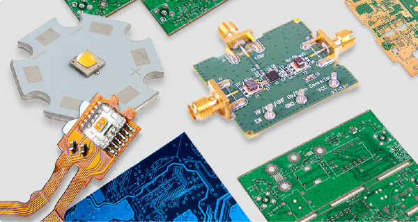
How does PCB milling work for RF, flex, and advanced materials beyond FR4?
RF designs frustrate traditional mills. Flexible materials buckle during cutting. Ceramic substrates shatter easily. Each advanced material breaks standard milling rules. Special handling prevents expensive failures.
RF materials require precision isolation. Flexible boards need low-stress fixturing. Ceramics demand gentle shallow passes. I adapt milling protocols through four key modifications for each material type.

Radio Frequency Boards
RF circuits need precise impedance control. I mill isolation trenches differently. Deeper cuts maintain signal integrity. Slower feed rates ensure perfect edges. Material choices matter too:
- FR4 causes signal loss at high frequencies
- Rogers substrates mill cleaner for RF circuitry
- Sharper tools maintain consistent trace geometry
Flexible Circuit Approaches
Standard vacuum beds crush thin materials. I use adhesive backing instead. Milling depth control prevents cutting through flex layers. Consider these adjustments:
| Flex Material | Fixturing Solution | Max Cut Depth |
|---|---|---|
| Polyimide | Low-tack adhesive | 0.25mm |
| PET film | Double-sided tape | 0.18mm |
Ceramic Material Handling
Brittle ceramics crack easily. I run multiple shallow passes. Coolant prevents thermal shock. Diamond-coated tools last longer against abrasive surfaces. Test stress points before full production.
Each material demands specific protocols. RF boards prioritize isolation precision. Flex circuits need non-distorting fixturing. Ceramics require gentle machining approaches. Document settings for repeat orders.
Conclusion
PCB milling costs balance prototype flexibility against production efficiency. Match equipment and settings to your material requirements and volume. Smart choices minimize expenses at every scale.

