
Electronics often fail because of flimsy connections. Frustrating errors creep in when signals get interrupted. Understanding PCB connector types saves you hours of troubleshooting.
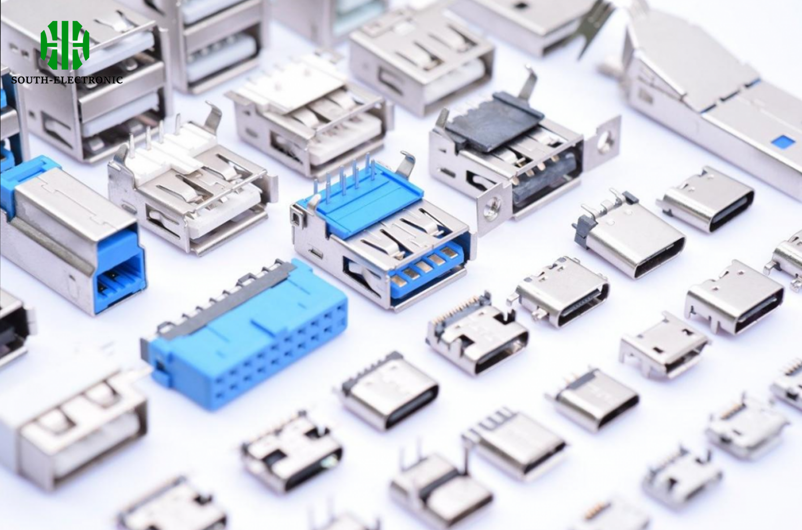
PCB connectors group into three main types: board-to-board joins PCBs directly, wire-to-board attaches cables to circuits, and wire-to-wire links cords without boards. Within these, you find specialized varieties like card-edge, USB, or high-power connectors for electronics.

This breakdown simplifies selections. Let’s dive deeper into choosing connectors for specific needs.
How to choose between board-to-board and wire-to-board connectors?
Are you risking space limitations or external connection needs? Confusing these two types creates messy boards.
We pick board-to-board for internal device links. Choose wire-to-board for cable-PCB attachments.
Key Selection Factors
| Consideration | Board-to-Board Use Case | Wire-to-Board Use Case |
|---|---|---|
| Space Needs | Compact stacking or layered PCBs | Cables entering board surfaces |
| Signal Flow | Direct board communication | External device interfacing |
| Assembly Stage | Factory machine placement | Field-serviceable connections |
| Common Examples | Mezzanine connectors in servers | IDC ports on drones |
| Vibration Risks | Low (permanent joints) | Higher (cables cause strain) |
PCB layouts dictate the choice. Board-to-board shines in vertical configurations. Modern laptops stack memory modules this way. Wire-to-board handles power and signal cables. Think of sensors wiring into industrial dashboards. Both save space but target different points. Internal electronics favor direct board linking. External features rely on cable attachments. Match each to the connection purpose, not convenience.
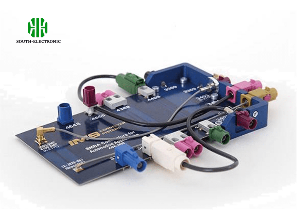
Which rugged connectors survive harsh environments?
Ordinary connectors melt, rust, or crack under stress. Industrial and outdoor applications demand toughness.
We select IP-rated, locking, or military-grade circular connectors. They tolerate water, dust, and extreme temperatures.
Survival Design Elements
Survivors share core traits:
- Sealing Systems: Rubber gaskets block moisture ingress. IP67 or IP68 ratings prevent dust/water entry
- Material Resilience: Stainless steel shells resist chemical corrosion in marine or factory settings
- Lock Mechanisms: Twist-lock features maintain connections during constant vibration
- Thermal Limits: Silicone insulation protects contacts from -40°C to 125°C extremes
Military-spec connectors pass shock/vibration tests. Rectangular hybrids combine metal housings and sealed contacts. Applications prove their endurance. Oil rig sensors need waterproof integrity. Railroad systems rely on vibration proof attachments. Aerospace uses MIL-DTL-38999 series connectors. Match environment severity to the connector’s rating. Never rely on consumer-grade parts near extreme conditions.
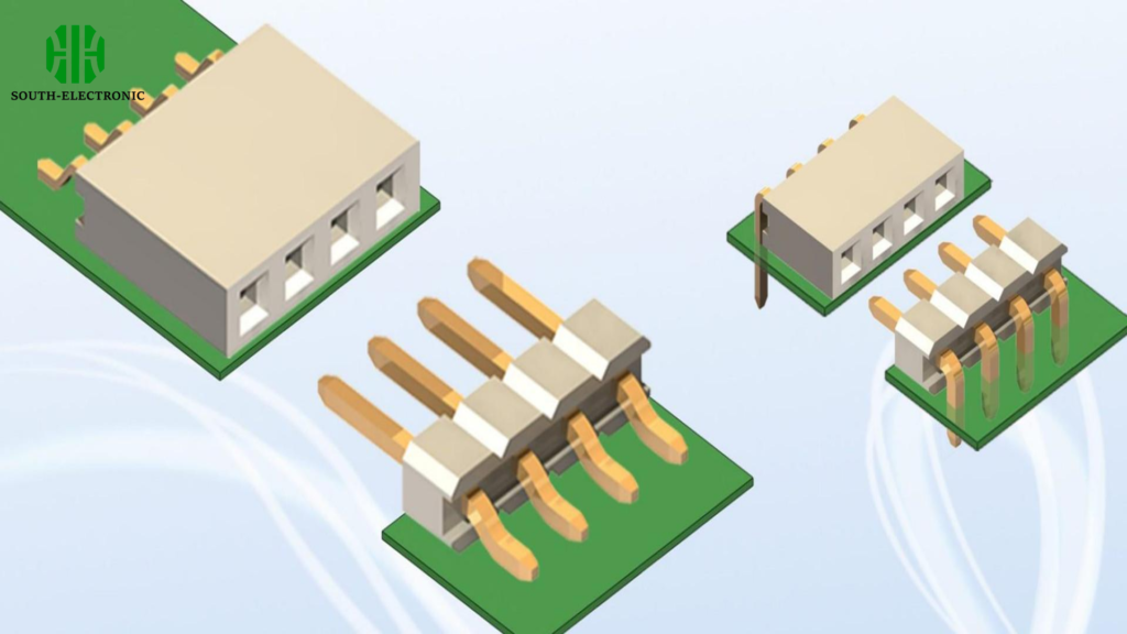
Are spring-loaded and press-fit connectors better than solder?
Soldering burns components or creates brittle joints. Alternatives offer simplicity and rework ease.
We prefer spring-loaded/press-fit for prototyping. Solder wins for permanent high-reliability bonds.
Connection Method Breakdown
| Method | Strengths | Weaknesses | Best Deployment |
|---|---|---|---|
| Spring-Loaded | Rapid testing; zero tools needed | Contact wear after 500 cycles | Labs; sample validation |
| Press-Fit | High-volume automation friendly | Hole tolerance sensitivity | Consumer electronics mass production |
| Soldering | Lowest long-term failure rates | Thermal damage risks | Aviation; power systems |
Spring connectors avoid heat stress. Pogo pins connect test boards repeatedly. Press-fit pins suit automotive computers. They insert into plated holes sans solder flow. However, vibration shakes them loose faster than solder. Soldering forms unbreakable bonds in infrastructure gear. Each approach serves distinct needs. Balance convenience against connection permanence.
Conclusion
Select PCB connectors by function: connection type, environment toughness, and assembly method. Smart choices prevent electronic headaches.

