
Picking the wrong PCB substrate can ruin your circuit board. Failed prototypes. Overheated components. Costly redesigns. Let’s cut through the confusion. I’ll explain the core materials that bring circuits to life.
PCB substrates include FR-4 (standard), polyimide (flexible), ceramic (high-temperature), and Rogers (high-frequency). Each offers unique thermal, mechanical, and electrical properties. Match the material to your project’s voltage, heat, and signal needs for optimal performance.
Choosing a substrate feels overwhelming, but it’s simpler when you break it down. Let’s explore the key materials and their hidden tradeoffs. By the end, you’ll know exactly which one fits your design.
What Are the Most Common PCB Substrate Materials and Their Key Properties?
Ever stared at material specs and felt lost? I’ve burned boards with poor choices. Let’s decode the big four substrates every designer uses.
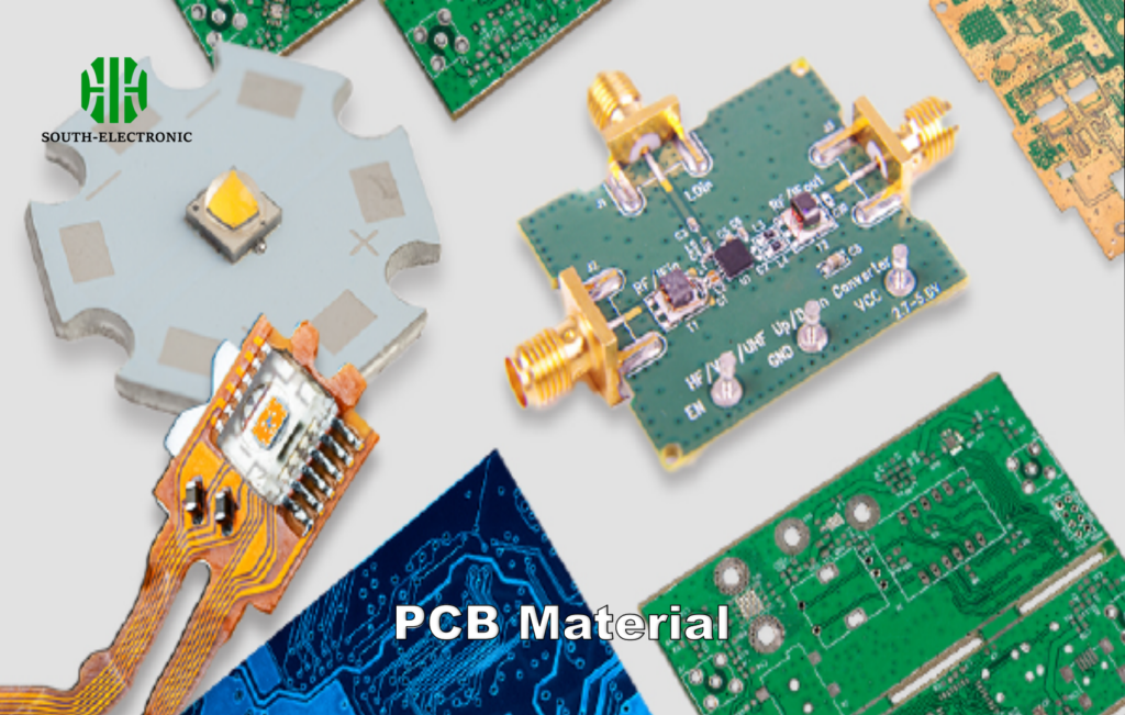
FR-4 (fiberglass epoxy), polyimide, ceramic, and Rogers are top PCB substrates. FR-4 balances cost and performance. Polyimide bends. Ceramic withstands extreme heat. Rogers excels in 5G/wireless apps. Dielectric constants range from 3.5 (Rogers) to 6+ (ceramics).
Material Breakdown
Let’s dissect what each material does best:
| Material | Thermal Conductivity | Max Temp (°C) | Cost | Best For |
|---|---|---|---|---|
| FR-4 | 0.3 W/mK | 130 | $ | Budget boards |
| Polyimide | 0.2 W/mK | 260 | $$ | Flex circuits |
| Ceramic | 24 W/mK | 800 | $$$$ | High-power LEDs |
| Rogers 4350 | 0.6 W/mK | 280 | $$$ | RF antennas |
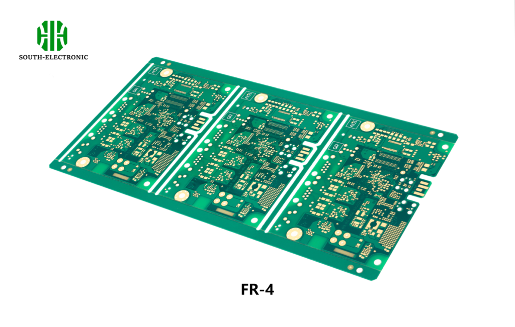
FR-4 works for 90% of consumer electronics. Its glass-reinforced epoxy handles basic heat and voltage. But I once fried a drone controller using FR-4 near motors—it couldn’t handle sustained 120°C.
Polyimide saved my smartwatch flex PCB project. It bends 360° without cracking. Tradeoff? Poor heat dissipation. Attach a heatsink if using power components.
Ceramic substrates (AlN, Al₂O₃) shine in laser diodes and automotive inverters. I measured 80°C drops vs FR-4 in LED arrays. But costs 4x more.
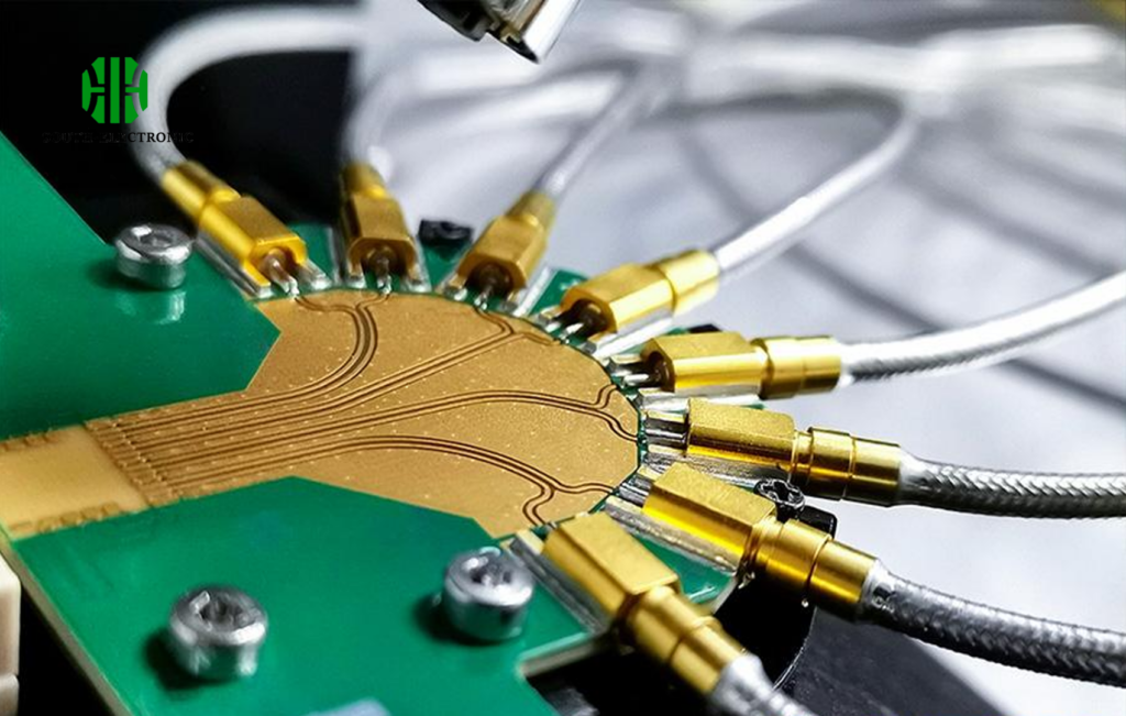
Rogers 4000 series kept my 28 GHz radar stable. Low dielectric loss (0.0037 vs FR-4’s 0.02) prevents signal fade. Perfect for millimeter-wave.
How to Choose the Right PCB Substrate for Your Application?
I once wasted $2k on ceramic boards for a toy remote. Learn from my mistakes. Use this decision tree.
Prioritize operating temperature, signal frequency, flex needs, and budget. For under 1 GHz and <130°C, FR-4 works. High-frequency (5G, radar) needs Rogers. Bendable? Polyimide. Extreme heat? Ceramic. Never overspend on specs you don’t need.
Step-by-Step Selection
-
Thermal Requirements
- Power LEDs/Servers → Ceramic (24 W/mK)
- Medium (IoT sensors) → FR-4 (0.3 W/mK)
- Low (Wearables) → Polyimide
-
Mechanical Needs
- Foldable devices → Polyimide (500k bend cycles)
- Rigid boards → FR-4/Ceramic
-
Signal Speed
- 30 GHz → Megtron 6 (Dk=3.2)
-
Budget Limits
- Prototypes → FR-4 ($5/board)
- Mass production → Compare cost/performance
Mismatched Dk (dielectric constant) causes signal reflection. In my WiFi 6 router, using FR-4 instead of Rogers caused 15% speed loss. Match Dk to frequency.
Why Is FR-4 Dominant in PCBs?
Walk into any PCB fab, and you’ll see FR-4 everywhere. But why? I tested 6 materials to find out.
FR-4 dominates due to low cost ($2/sqft), multi-supplier availability, and balanced performance. It handles 1-4 layer boards well, resists moisture, and suits 90% of applications below 130°C. Even with limitations, it’s the “good enough” choice.
FR-4 Pros vs Cons
Pros
- Cost: 5x cheaper than Rogers
- Process: All fabs support it
- Repairable: Easy rework vs ceramics
Cons
- Thermal limit: Fails above Tg (130-180°C)
- Signal loss: Tan delta 0.02 (poor for GHz+)
- Brittle: Cracks under repeated stress
During a power supply design, FR-4’s Tg (glass transition temp) bit me. At 110°C ambient, the board warped. Had to switch to high-Tg FR-4 (180°C). Still cheaper than ceramics.
For RF projects, I blend FR-4 with Rogers layers. Use Rogers for antenna sections, FR-4 elsewhere. Cuts costs 30%.
How Does Substrate Material Impact PCB Performance and Reliability?
I crashed a drone due to substrate failure. The moral? Material choice isn’t theoretical—it’s survival.
Substrates control heat dissipation, signal speed, and mechanical durability. High-Dk materials slow signals. Poor thermal conductivity cooks components. Flexibility prevents fracture in moving parts. Moisture absorption (FR-4: 0.1%, Ceramic: 0%) affects outdoor reliability.
Critical Impact Areas
| Issue | FR-4 | Ceramic | Polyimide |
|---|---|---|---|
| Signal Loss | High at 10 GHz | Medium | Low |
| Heat Build-up | Rapid | Minimal | Moderate |
| Moisture Resistance | Good (0.1%) | Excellent (0%) | Poor (1.5%) |
| Vibration Survival | 2/5 | 4/5 | 5/5 |
In automotive PCBs, I use ceramic-based metal-core boards. They handle engine heat (140°C) and vibration. Polyimide cracks in cold (-40°C).
Dk inconsistency causes phase errors. I measured 0.15mm Rogers thickness variation → 12° phase shift at 24 GHz. Demand tight tolerances for high-frequency.
Conclusion
Match PCB substrate to thermal, mechanical, and electrical needs. FR-4 covers basics, Rogers for RF, polyimide bends, and ceramic conquers heat. Test prototypes—your application decides the winner.

