

Struggling with electronic component limitations? Poor connections cause overheating? Ball grid array packages solve these issues in modern compact devices—but require special handling.
BGA packages deliver higher connection density, superior electrical performance, and better heat dissipation than legacy options. However, they need X-ray inspection for hidden joints and complicate repairs due to their under-chip solder ball configuration.
Understanding BGA pros and cons is just the start. Let’s explore crucial techniques for handling these powerful yet complex components.
How to Successfully Solder BGA Components?
Frustrated by BGA soldering failures? Cold joints ruin perfectly placed components? Follow three critical control steps for zero-defect results.
Proper soldering relies on temperature control (ramp rates below 3°C/sec), consistent paste deposition via stencil, and component-level preheating. Always use void-free flux formulations designed for ball grid array soldering processes.
Precision Techniques for Reliable Connections
Here’s how to approach each stage:
| Phase | Critical Factors | Failure Prevention |
|---|---|---|
| Preparation | PCB pad oxidation removal | Plasma cleaning + nitrogen purge |
| Placement | Sub-millimeter ball alignment | Fiducial markers + JIGS |
| Reflow | Thermal profile uniformity | Zone-controlled oven + sensors |
Preparation matters most. I once scrapped a batch when residue caused bridging. Now I clean boards twice before applying solder paste. Consistent flux application is mandatory—too little prevents fusion, too much creates voids. For placement, alignment tools ensure each ball contacts the pad correctly. The reflow phase needs gradual temperature increases. Sudden heating causes component warping. Follow manufacturers’ thermal curves precisely. Post-soldering inspection verifies all joints formed properly before proceeding. Training is key—unskilled operators create expensive waste.
Why is X-Ray Inspection Critical for BGA Assembly Quality?
Can’t see defects hidden under chips? Visual inspections miss critical failures? X-ray analysis reveals hidden ball grid array soldering flaws instantly.
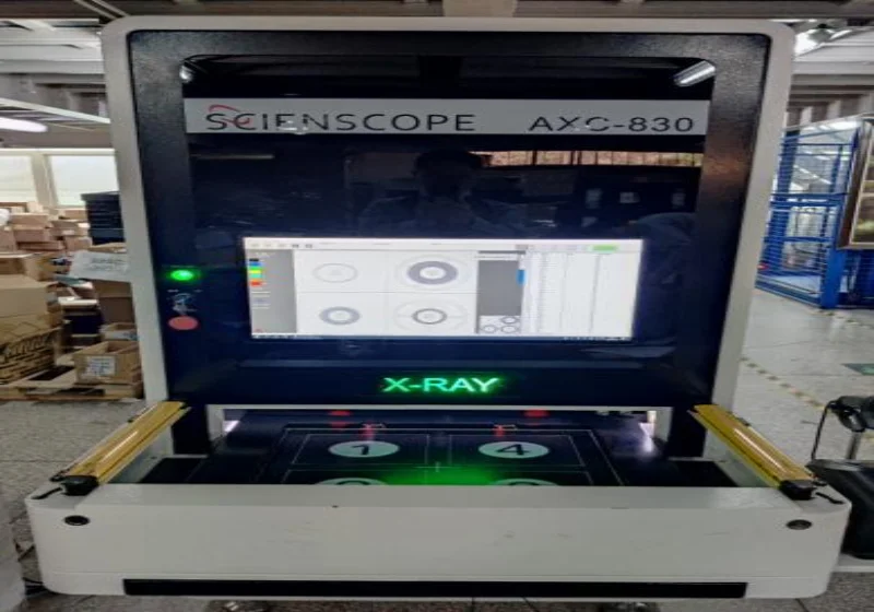
X-ray identifies voids, cracks, and bridging within BGA joints that optical methods can’t detect. This non-destructive technique prevents latent field failures and reduces board rejection rates in automated assembly lines.
Defect Identification and Prevention
| Defect Type | X-Ray Identification | Corrective Action |
|---|---|---|
| Voids | Spherical dark spots | Paste storage humidity control |
| Bridging | Irregular joint connections | Stencil thickness optimization |
| Cracks | Jagged fracture lines | Post-reflow cooling adjustments |
Voids larger than 25% compromise thermal transfer. I enforce moisture-controlled paste storage to minimize this after finding bubbles in 30% of chips. Bridging appears as fused balls instead of uniform arrays—often from excessive paste volume. Crack detection requires magnification to see micro-fractures during thermal cycling testing. Automatic X-ray machines flag failures in real time. Operators view 3D sectional views showing layer-by-layer results. This process confirms even tiny joints under the ball grid array package meet specifications. Combine it with AOI (Automated Optical Inspection) for complete coverage.
BGA vs. LGA: Which CPU Package Delivers Better Performance?
Choosing the wrong processor package? Heat throttling limits your device? Compare core functional differences before selecting socket types.
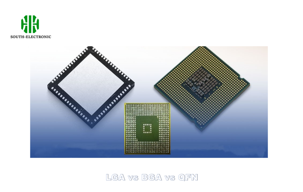
For raw performance: ball grid array dominates due to shorter electrical paths. For serviceability: LGA (Land Grid Array) wins with user-replaceable CPUs. Heat dissipation favors BGA’s full-board contact and ball grid array socket designs.
Technical and Practical Comparison
| Attribute | BGA | LGA | Winner |
|---|---|---|---|
| Signal Distance | <1mm vertical height | Socket-induced gaps | BGA |
| Thermal Transfer | Direct PCB conduction | TIM material layers | BGA |
| Repairability | Requires reflow | Slide-lock sockets | LGA |
| High-Frequency | Low inductance | Signal reflections | BGA |
Signal distance dictates speed. BGA mounts directly to pads with minimal distance—ideal for 5GHz+ CPUs. LGA packages use pressure contacts that add resistance. Thermal tests show BGA’s direct copper conduction lowers temperatures by 8-12°C versus equivalent LGAs. However, field-replacing a faulty BGA CPU destroys the board. I always advise clients: choose ball grid array for integrated mobile designs, prefer LGA for upgradable systems. LGA permits user-swappable chips using retention brackets and springs. Both work in servers, but thermal throttling favors ball grid array packages for dense compute applications.
Conclusion
BGA packages offer unmatched density and electrical properties, but demand precise soldering and inspection expertise. Choose wisely based on repair needs and thermal requirements.

