
Ever had your gadget fail because wires lost connection? That sinking feeling is why PCB connectors matter. They silently keep electronics alive.
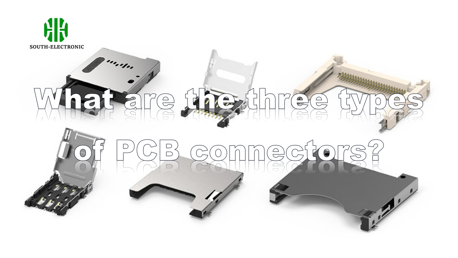
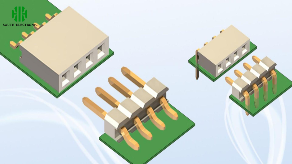
Three core PCB connectors are board-to-board, wire-to-board, and wire-to-wire types. Board-to-board links circuit boards together. Wire-to-board plugs cables into a PCB. Wire-to-wire joins two cables directly. Choosing correctly prevents device failures.

Connectors seem simple but cause big headaches when wrong. After learning the basics, see how problems happen and how pros install them. Let’s uncover these struggles and solutions step by step.
What are common PCB connector problems?
Do connectors suddenly disconnect mid-use? Loose pins or corrosion quietly sabotage electronics daily. They create false signals and power drops.
Frequent issues include contact loosening from vibrations, corrosion from moisture, pin misalignment, solder cracks, and wear from physical mating cycles. These cause intermittent failures, signal errors, or total power loss in circuits.
Understanding these flaws helps prevent device crashes. I’ve fixed many projects where cheap connectors broke after six months. Let’s dissect risks and protection tactics.
Failure triggers and prevention table
Wear isn’t random – see exactly what kills connectors:
| Cause | Effect | Prevention |
|---|---|---|
| Vibration | Contacts loosen over time | Use locking clips/strain relief |
| Humidity | Metal pins oxidize & corrode | Apply conformal coating |
| Insertion force | Plastic housing cracks | Follow mating-cycle specifications |
| Solder stress | Joint fractures under heat | Reflow correctly with supports |
Vibration attacks automotive and industrial gear most. I add adhesive dots to secure sockets in DIY drones. For humid places like bathrooms, silicone sealants block moisture seeping into copper pins. Mating cycles matter too. Each plug-in scrapes metal contacts slightly thinner. Over months, resistance creeps up. Cheap units last under 500 cycles. Spend extra for 5,000-cycle rated parts.
Solder cracks sneak up slowly. Thermal expansion pulls joints apart where pins meet boards. I reinforce these spots with epoxy glue. Thick wires strain ports heavily. Always clamp cabling 5mm from exit points. Prevention beats frustrating repairs later.
How to remove PCB connectors?
Stuck connectors snap pins if forced carelessly. I’ve destroyed tiny ports trying quick yanks. Patience and tools win here.
Key steps: Desolder pin joints first if possible. Use pliers for pull tabs. Never twist vertical force! For stubborn cases, apply hot air at 300°C gradually to soften adhesive before lifting gently.

Removal varies by connector style. My first attempts melted plastic housings before I learned these tricks.
Method table and key cautions
Different connectors demand tailored approaches:
| Connector Style | Tools Required | Risk If Wrong |
|---|---|---|
| Through-hole | Soldering iron, suction pump | Lifted pads from overheating |
| SMD (surface mount) | Hot air station, tweezers | Component warping/cracking |
| Press-fit | Extraction pliers | Bent pins or board damage |
Through-hole types anchor best but need careful desoldering. Heat one pin fully then suction molten solder out fast. Repeat per pin – skip shortcuts. Rushing overheats copper traces until they flake off boards. Surface-mount connectors melt glue underneath first. Point hot air nozzles at 45-degree angles for gentle warming. I count 8 seconds then test wiggle looseness. Press-fit connectors just grip friction-tight. Wiggle pliers perpendicularly without bending pins.
My golden rule: Pull force below 2 Newtons or use heat. Check manufacturer datasheets – Molex posts extraction guides for each product code online. Save broken units to practice repair techniques before real jobs. Protect nearby capacitors especially during heating phases.
How to evaluate PCB connector suppliers like Molex, Smiths, and others?
Ever ordered connectors that arrived broken late? Vetting vendors avoids chaos. I check samples hard before big orders now.
Assess suppliers on delivery speed, manufacturing precision, certifications, pricing scales, and defect rates. Reliable firms provide material test reports, offer custom designs, and guarantee lead times under 4 weeks consistently.
Big names differ wildly in strengths. I map needs to their specialties before deals.
Rating critical criteria
Balance cost against these non-negotiables:
| Factor | Ideal Standard | Testing Trick |
|---|---|---|
| Material purity | ≤0.5% impurities in copper | Microscope solderability test |
| Accuracy | ±0.02mm dimensional gaps | Caliper random batch samples |
| Documentation | Full UL/CE/ISO compliance | Request certification copies |
| Shipping reliability | 99% on-time rates | Trial order small batches first |
Price isn’t everything – Molex excels in automotive-grade robustness but costs 30% more than basic Asian imports. Smiths supplies niche military-spec units faster. For hobbyists, I recommend TE Connectivity for affordability testing.
Test plating adhesion by scratching pins lightly. Poor coatings flake easily. Ask suppliers for IPC-6010 ratings. High-reliability designs need class 3 certification. I always check solder cup depth consistency too. Mismatches cause cold joints. Call their tech support with questions. Fast expert replies signal trustworthy partners.
Conclusion
Pick board-to-board, wire-to-board or wire-to-wire connectors precisely. Prevent failures through smart removal habits and tough supplier vetting. Robust connections save endless repair time.

