
Ever push your graphics card too hard? Flickering screens and crashes happen. Frustration sinks in. The solution lies deeper than silicon – inside the engineering marvel of the GPU PCB itself.
Modern high-performance GPU PCBs integrate layered structures, specialized materials, and meticulous power delivery systems for stability. Key elements include: 6-12 layer stackups with dedicated power planes, 90%+ pure copper traces, and voltage regulation modules (VRMs) designed for thermal efficiency – all essential for graphics card PCB reliability.
Now that we’ve covered the basics, let’s break down three critical engineering aspects that transform ordinary PCBs into powerhouse performers. Each feature impacts stability when pushing your hardware to its limits.
Why Do PCB Material Choices Dictate GPU Overclocking Potential?
Overclocking crashes your system suddenly? Cheap laminate warps under heat. That instability costs you benchmark scores. Premium materials provide solutions.
PCB substrate quality directly impacts thermal handling and signal speed. High-Tg (glass transition) materials like Isola FR408HR withstand 180°C+ temperatures. This prevents warping and maintains signal paths even during extreme overclocks in graphics card PCB designs.
Material Properties That Unlock Stability
Every modern GPU PCB relies on specialized laminates that balance three core requirements:
| Property | Budget Material | Performance Material | Impact |
|---|---|---|---|
| Thermal Conductivity | 0.3 W/mK | 0.5-0.8 W/mK | Heat dissipation speed |
| Dielectric Constant | 4.5+ | 3.8-4.2 | Signal propagation rate |
| Decomposition Temp | 280°C | 340°C+ | PCB longevity |
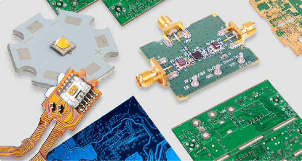
High-frequency signals require smooth pathways. Rogers 4350B laminates offer stable dielectric constants across frequencies. These reduce signal loss during data transfers to GPU memory. Thermal management matters equally. Anodized aluminum cores in some 50 series card PCB designs spread heat better. This prevents localized hot spots on ATX form cards. Layer transition quality affects everything. Resin-rich prepreg bonds ensure no air pockets between layers. Good bonds combat delamination when your ATX form card heats repeatedly. Premium materials demand higher costs but prevent throttling during peak workloads.
How Many Layers Does a Modern Graphics Card PCB Actually Need?
Your current PCB video card struggles with 4K gaming? Signal interference causes artifacts. Insufficient layers create bottlenecks. More layers enhance performance.
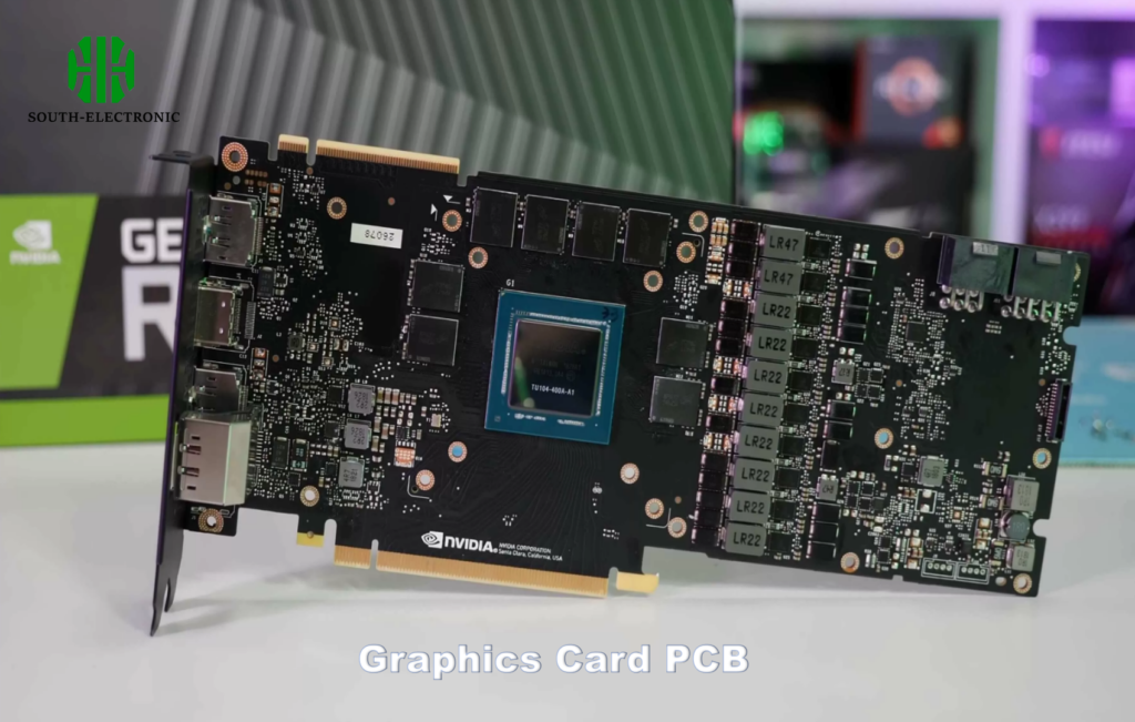
Mid-range GPUs use 6-8 layers while flagship models require 10-12 layers. This creates dedicated pathways for power, ground, and high-speed signals – reducing electrical noise and supporting complex routing for modern ICs.
Layer Allocation Strategy
PCB layer counts follow deliberate allocation patterns balancing three key functions:
| Layer Assignment | Typical Count | Core Purpose |
|---|---|---|
| Signal Layers | 4-6 | GPU/memory trace routing |
| Power Planes | 2-3 | Stable voltage distribution |
| Ground Planes | 2-3 | EMI shielding and thermal dissipation |
Power delivery requires separation. Dedicated planes create low-impedance paths for GPU core and VRAM. This prevents voltage drops when currents spike suddenly. Signal separation proves equally crucial. High-frequency GDDR6X traces need isolation from noisy digital circuits. Shielding layers cut electromagnetic interference (EMI). Thermal stress management affects layer thickness. Heavy copper layers (up to 3oz) on power planes handle 400W+ loads without heating excessively. Modern ATX form cards often use thinner layers (0.8mm vs 1.6mm). Thin builds require precise layer control to prevent warp during reflow soldering.
Can PCB Layout Alone Solve GPU Power Delivery Challenges?
Voltage drops crash your system during gaming peaks? Perfect layouts still fail with weak components. Power challenges require holistic approaches.
PCB trace routing matters critically but cannot overcome inadequate VRMs. Optimal solutions combine: 16-phase power designs with 50A DrMOS chips, strategic decoupling capacitor placement, and carefully calculated copper pour areas to minimize resistance and inductance.
Power Delivery System Synergy
Three interdependent factors determine power stability in pcb video cards:
Component Synergy Layout
- Phase controller placement within 15mm of VRMs
- Decoupling capacitors sandwiched near GPU socket
- Current balancing across parallel phases
Trace Geometry Optimization
- 200+ mil width for CPU Vcore input lines
- 45-degree bend angles to reduce impedance jumps
- Length-matched pairs for multi-phase stability
Thermal Mitigation Tactics
- Thermal vias under MOSFETs connecting to backplate
- Exposed copper pads with thermal paste contact
- Thermal sensors placed at hotspot regions
Copper weight proves critical. Thick 3oz layers for PWR_GDN nets prevent impedance buildup during 500W+ transients. Vcore paths need short vertical jumps to inner-layer planes. This avoids overheating thin surface traces. Even perfect layout fails with subpar components though. Digital PWM controllers beat analog ones in modern 50 series card PCB designs, enabling millisecond-level adjustments. Proper component matching remains irreplaceable for graphics card PCB integrity.
Conclusion
High-performance GPU PCBs combine specialized materials, 10+ layer designs, and tuned power circuitry. These elements create the backbone for reliable, stable operation in demanding tasks and overclocking.

