
I’ve seen many PCBs struggle with noise issues. Messy grounding hurts every signal. Star grounding offers an escape path. This technique stops ground loops quietly.
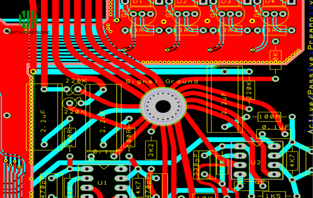
Star grounding connects separate ground paths to one point like star rays. This prevents conflicting currents sharing paths. It lowers noise by giving each section its private ground highway back home. Proper star grounding squashes EMI monsters hiding in your electronics.
Ready to dive deeper? We’ll explore routing tricks and common traps. Don’t skip the critical EMI insights coming next.
How to route star grounding on single and multi-layer PCBs?
Single-layer PCBs frustrate me easily. You juggle wires in cramped space. Routing stars needs planning. But it saves prototypes from noisy disasters.
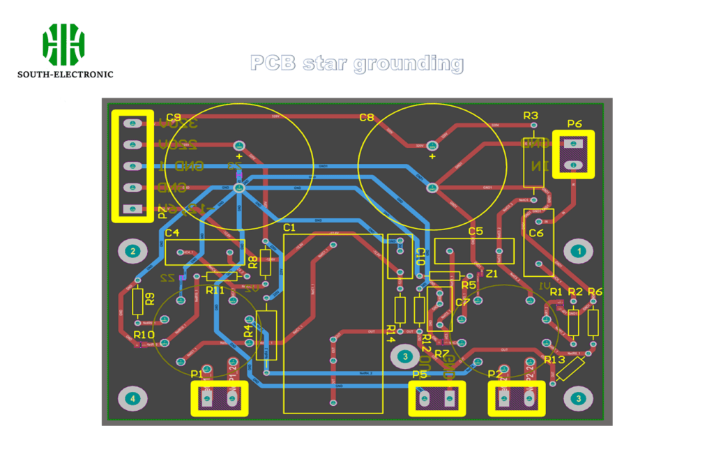
Star grounding works by connecting all grounds to a center pin or plane. For single-layer boards, use radial traces avoiding loops. Multi-layer designs bury dedicated ground layers for cleaner paths.
Key Routing Strategies
Divide designs into zones like power, analog, and digital. Route each zone’s ground separately first. Then unite them at one meeting point. Avoid sneaky loops.
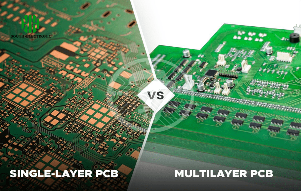
Single vs Multi-Layer Techniques
Critical differences exist between layer types:
| PCB Type | Method | Watch Outs |
|---|---|---|
| Single-layer | Radial copper traces | Avoid crossing signal lines |
| Double-layer | Bottom layer as ground plane | Use vias judiciously |
| 4+ layer | Dedicated internal ground plane | Isolate noisy sections |
In single-layer boards, I sketch star patterns before routing power traces. Leave clearance around the central grounding pad. Multi-layer boards shine with internal ground planes. Connect sections using vias to this hidden highway. Always keep return paths short. Measure trace lengths to balance impedance. Test voltage drops between distant points.
What are the top 6 star grounding mistakes that keep your circuit noisy?
Grounding errors haunt my lab nightmares. One misplaced trace fuels hours of debugging. Star grounding fails when we ignore current clashes. These mistakes birth noisy circuits.
Top errors include mixing digital/analog grounds and creating hidden loops. Forgetting high-current paths also distorts signals. Each error has simple fixes.
Why Mistakes Happen
Rushed layouts skip ground planning. Auto-routing tools create chaos. Designers forget current return paths matter most.
Mistake Breakdown
Here are the troublemakers and solutions:
| Mistake | Why It’s Bad | Fix |
|---|---|---|
| Multiple star points | Creates ground loops | Single reference point only |
| Daisy-chained connections | Shared impedance causes noise | Radially route from center |
| Ignoring return path lengths | High-frequency signals suffer | Shorten critical ground traces |
| Mixing analog/digital grounds | Cross-contamination of noise | Separate then meet at star |
| Poor component placement | Forces long detours | Cluster by ground zone |
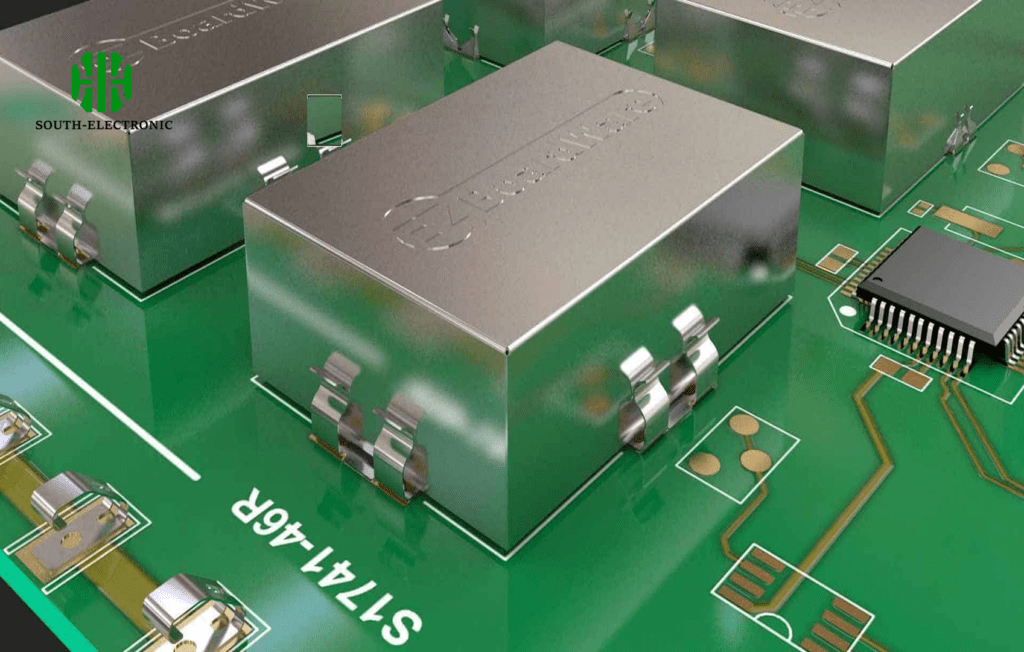
| Forgetting shield grounds | EMI sneaks in through gaps | Dedicated star branch |
High-current components like motors need thick traces back to the star. Place noisy ICs near the center point during layout. Test resistance between ground points. I’ve fixed boards by adding a $0.02 resistor to isolate audio circuits. Validate with spectrum analyzer sweeps.
Can star grounding really suppress EMI?
EMI nightmares disrupt my sleep. Floating grounds act like radio antennas. But critics question star grounding’s real power. Does this technique crush interference?
Yes, when done properly. Star grounding slices problematic ground loops. It blocks EMI escape routes. My oscilloscope proves cleaner signals post-implementation.
EMI Reduction Mechanism
Star grounding shrinks loop areas where EMI breeds. Currents don’t circle endlessly. The single-point return quiets electromagnetic chatter.
Practical Implementation Factors
Effectiveness depends on three layers:
| Factor | High Success Scenario | Low Success Scenario |
|---|---|---|
| Frequency range | Below 50MHz | Microwave/RF designs |
| Layout discipline | Strict zoning | Compromised star point |
| Board complexity | Moderate component count | 1000+ components |
Star grounding works best under 50MHz. Above this, ground planes dominate. I reserve it for mixed-signal boards with sensitive audio/ADC sections. Combine with power supply decoupling caps near noise sources. Measure EMI before/after implementation. In a motor controller project, star grounding cut noise by 12dB.
Conclusion
Star grounding solves grounding chaos when properly executed. Use it strategically across PCB layers. Avoid the six deadly mistakes for quieter results. Measure your EMI gains.