
Ever tried building electronics without a strong foundation? Your components shift or break, causing endless frustration. A rigid PCB solves this through solid structural support.
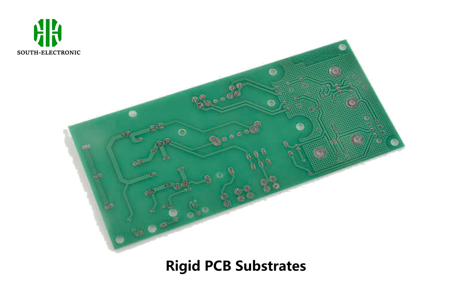
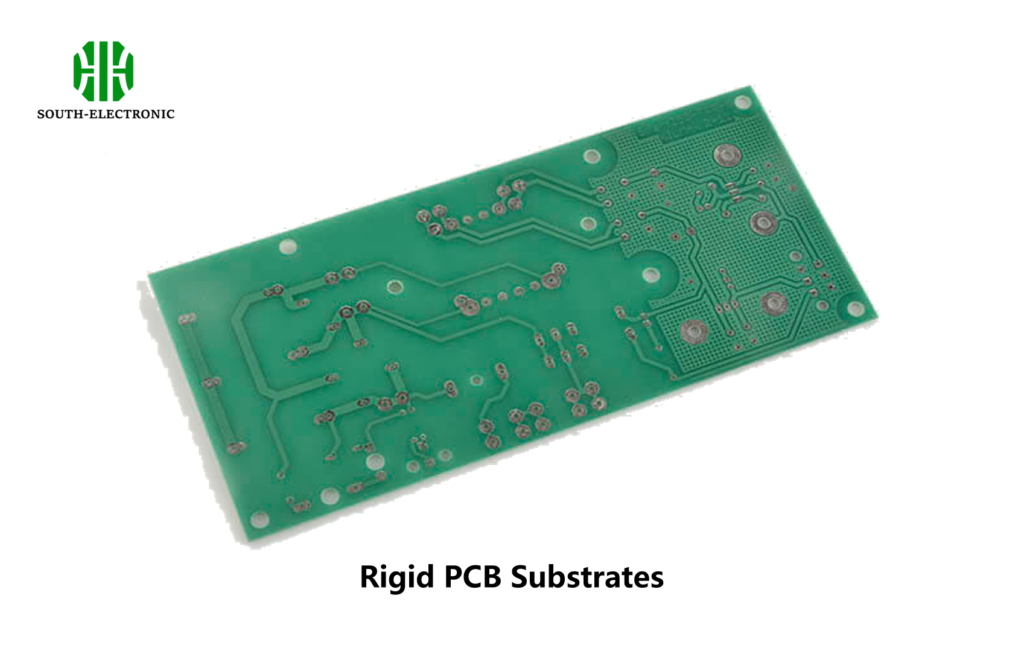
A rigid circuit board provides an inflexible base for mounting electronic components. Made from materials like FR4 epoxy, it ensures stability and reliable connections in devices like computers or medical equipment where movement isn’t needed.
Now that you understand the basics, choosing the right type is critical. Let’s explore single-sided, double-sided, and multi-layer options for your next project.
Do you need single-sided, double-sided, or multi-layer rigid PCBs?
Struggling with complex circuitry in tight spaces? Component crowding ruins functionality. Matching your board’s layers to your project prevents this mess.
Choose single-sided for basic circuits, double-sided for moderate complexity, and multi-layer for advanced electronics. Layers increase routing options while keeping boards small.

Key differences between layer types
Here’s a clear way to decide your PCB structure:
| Type | Best For | Cost | Limitations |
|---|---|---|---|
| Single-sided | Calculators, toys | $ Lowest | Limited component space |
| Double-sided | Power supplies, IoT | $$ Medium | Requires precise alignment |
| Multi-layer (4+) | Smartphones, servers | $$$ Highest | Complex manufacturing process |
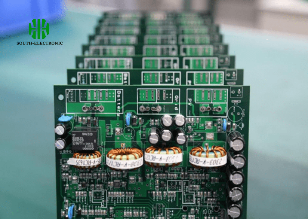
Single-sided boards have copper on only one side. They’re good for simple items. Double-sided boards connect through holes between layers. This works well for home appliances. Multi-layer designs stack like sandwiches. They fit complex devices despite small size. I once tried forcing advanced circuits into single layers — the overheating taught me that dense designs demand layered solutions.
How much does a rigid circuit board cost?
Seeing unexpectedly high PCB quotes? Pricing confusion often delays projects. Understanding cost factors saves both money and headaches.
Standard FR4 boards range from $5-$50 based on specs. Key cost drivers include size, layer count, and special features like high-frequency materials for better signal reliability.
Three main pricing aspects
-
Materials matter
Standard FR4 epoxy is cheapest. Aluminum-backed boards cost 20% more for heat dispersion. -
Processing complexity
Tiny holes under 0.3mm or multiple copper layers require specialized drills, increasing labor time. -
Quantity discounts
Prototypes cost $20-$80 per board, but ordering 100+ units slashes prices by 60%.
Material thickness also impacts cost. Thick boards endure industrial environments but add expense for materials like heavy copper bases. Lead time choices matter too — urgent 24-hour orders trigger a 50% rush fee. Always submit detailed specs upfront to guarantee accuracy.
When should you consider rigid-flex alternatives instead of rigid PCBs?
Does your design bend or twist during operation? Cracked rigid boards are common in wearable gadgets. Failure happens when stiffness battles movement.
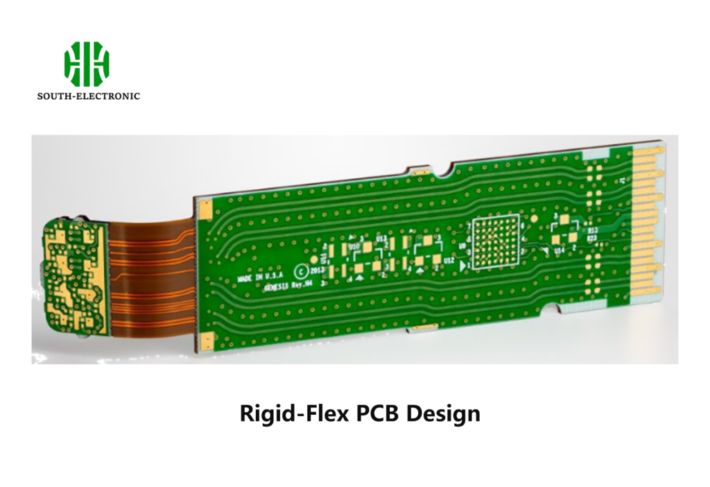
Switch to rigid-flex PCBs when devices need regular bending. They combine solid circuit boards connected by flexible strips. This hybrid approach prevents physical stress damage in things like robotics or foldable devices where constant movement occurs.
Comparison scenarios for better reliability
| Situation | Rigid PCB Risk | Rigid-Flex Advantage |
|---|---|---|
| Space restrictions (e.g., cameras) | Difficult routing | 3D folding reduces volume |
| Vibration environments | Solder joint fractures | Absorbs motion without cracking |
| Frequent assembly changes | Multiple boards need connectors | One-piece design streamlines work |
Military equipment often uses rigid-flex technology. Radios in soldier gear experience extreme movement. The rigid parts house microchips securely. Flexible sections handle bending between armor plates. Aerospace sensors show similar benefits — fewer connections mean better reliability during turbulence. But these hybrids cost 25% more initially. The investment ensures longevity through repeated motion cycles.
What testing methods check rigid PCB reliability?
Worried a flawed board might pass inspection? Hidden problems cause field failures. Rigorous testing prevents defective electronics from reaching customers.
Common tests include automated optical inspection (AOI) and in-circuit checking (ICT). These methods verify connections through precise electrical probing. They detect open circuits or incorrect component values for consistent quality.

Four essential verification techniques
-
AOI scanning
Cameras quickly scan boards for physical problems. Examples include missing solder or incorrect parts placement. -
Boundary scan testing
Checks integrated circuits communication using specialized pins. This validates complex chips. -
Functional testing
Tests the entire board by simulating real usage patterns. Power-up sequences are replicated. -
Environmental stress screening
Subjects boards to temperature cycling or vibration tests. This exposes weak points rapidly.
A client once skipped thermal cycle testing to save time. Their consumer boards failed after 3 months in warm climates. Rigorous inspection adds 15% to production time but prevents costly recalls. X-ray analysis also helps identify faults in multi-layer structures. Burn-in testing runs boards at high voltage over extended periods too.
Conclusion
Selecting proper rigid circuit boards involves understanding layers, costs, flexible options, and verification processes. Test thoroughly for dependable electronics.

