

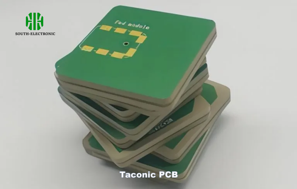
Ever struggled with signal loss in high-frequency circuits? Taconic PCBs solve this problem with specialized materials that outperform standard boards in RF applications.
Taconic PCBs use ceramic-filled PTFE and glass-reinforced substrates optimized for high-frequency signals. These materials provide stable dielectric constants[^1] and low signal loss[^2], making them essential for 5G systems and aerospace radar applications.
But what exactly makes Taconic PCBs stand out? Let’s break down their unique features and applications.
What Makes Taconic PCBs Different from Standard FR4 Boards?
FR4 boards fail in high-frequency environments. Taconic materials solve this with engineered dielectric properties perfect for RF stability.
Taconic PCBs use PTFE-based substrates with stable dielectric constants (±0.04 variation), unlike FR4’s inconsistent performance. This ensures precise impedance control for high-speed signals.
Key Differences Explained
Taconic PCBs are built for performance where FR4 boards fall short:
| Feature | FR4 | Taconic |
|---|---|---|
| Dielectric Constant | 4.3–4.8 (variable) | 2.2–10.2 (controlled) |
| Loss Tangent | 0.02 @ 1 GHz | 0.0009–0.002 @ 10 GHz |
| Thermal Stability | Deforms above 130°C | Stable up to 280°C |
| Applications | Consumer electronics | Radar, satellite systems |
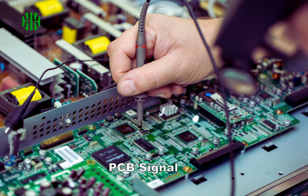
For example, a 10 GHz signal loses 30% less power on Taconic RF-35 than FR4. This is critical in phased-array antennas where signal integrity determines performance.
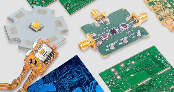
Why Do RF Engineers Prefer Taconic PCB Materials?
RF applications demand perfection. Taconic substrates deliver near-zero signal distortion for mission-critical systems.
Taconic materials minimize insertion loss (<0.2 dB/inch at 40 GHz) and maintain stable impedance across temperature swings, which FR4 and Rogers materials can’t consistently achieve.
Performance Drivers in RF Design
Three factors make Taconic the gold standard:
1. Low Dispersion[^3]
Taconic’s PTFE-ceramic mix minimizes frequency-dependent dielectric changes. A 6-layer Taconic board for a 28 GHz 5G base station showed <2% phase deviation over 24 hours.
2. Thermal Management[^4]
With a CTE (Coefficient of Thermal Expansion) matching copper (17 ppm/°C), Taconic prevents delamination in thermal cycling tests (-55°C to +125°C).
3. Manufacturability
Despite stiffness, Taconic laminates accept standard PCB processes better than pure PTFE. Hybrid materials like TLX-8 enable complex multilayer designs.
Which Taconic Material Grade Should You Choose?
Picking the wrong Taconic grade wastes budget. Match material properties to your frequency and thermal needs.
Use RF-35 for <6 GHz consumer devices, TLX-8 for 6–30 GHz radar, and TLY-5 for cost-sensitive mmWave prototypes needing <0.0015 loss tangent.
Material Selection Criteria
| Grade | Dk (@10 GHz) | Loss Tangent | Best For | Cost |
|---|---|---|---|---|
| RF-35 | 3.5 | 0.0020 | Base stations, automotive | $$ |
| TLX-8 | 2.55 | 0.0014 | Aviation radar | $$$$ |
| TLY-5 | 2.17 | 0.0009 | 60 GHz WiGig | $$$ |
I once used TLY-5 for a satellite uplink module. Its ultra-low loss tangent reduced noise by 18% compared to alternatives.
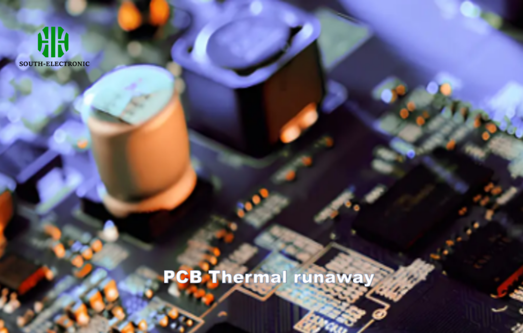
How Does Thermal Management Work in Taconic PCBs?
Overheating kills RF performance. Taconic’s thermal design keeps circuits cool under extreme loads.
Taconic laminates spread heat 3x faster than FR4 via ceramic fillers. Combined with metal-backed designs, they maintain stable Dk values even at 100°C+.
Heat Dissipation Strategies
-
Material Blending
Ceramic particles in Taconic TF-290 (20% alumina) improve thermal conductivity to 0.71 W/mK[^5] vs FR4’s 0.3 W/mK. -
Layer Stacking
Embedded copper coins in Taconic RF-45A carry heat away from power amplifiers:
| Layer | Material | Thickness |
|---|---|---|
| Top | Copper (2 oz) | 70 µm |
| Core | RF-45A | 0.5 mm |
| Baseplate | Aluminum | 3 mm |
- Airtight Packaging
Vacuum-sealed Taconic modules for space applications eliminate convective heat loss.
What Manufacturing Challenges Exist with Taconic Substrates?
Taconic’s benefits come with fabrication hurdles. Miss these steps and you’ll scrap entire batches.
Drilling Taconic requires carbide bits (not standard steel), and lamination demands strict temperature control (±2°C) to prevent PTFE degradation.
Production Pitfalls & Solutions
| Challenge | Risk | Fix |
|---|---|---|
| Material Softness | Drill wander/microscratches | Use 15° drill entry angle |
| PTFE Slippage | Layer misalignment | Plasma treatment pre-bonding |
| Copper Adhesion | Peeling traces | Laser ablation + chemical roughening |
| Via Filling | Air pockets in high-aspect vias | Conductive epoxy fill + vacuum assist |
A client once lost 200 boards due to untreated PTFE slippage. After switching to plasma cleaning, yield jumped to 98%.
Conclusion
Taconic PCBs offer unmatched RF performance via ceramic-PTFE blends. Choose grades wisely, master thermal designs, and adapt manufacturing techniques to leverage their full potential in high-frequency systems.
[^1]: Exploring the importance of stable dielectric constants will deepen your understanding of Taconic PCBs’ advantages in RF applications.
[^2]: Discover how low signal loss is crucial for the efficiency of 5G systems, highlighting the benefits of Taconic PCBs.
[^3]: Learn about Low Dispersion and its critical role in maintaining signal integrity in RF designs.
[^4]: Understand the significance of Thermal Management in RF PCB design and its impact on reliability and performance.
[^5]: Understanding the thermal conductivity differences can help in selecting the right materials for high-performance PCBs.

