
Imagine holding a smartphone where you can see light passing through its circuit board. Transparent PCBs make this possible, blending cutting-edge tech with futuristic design. But how do they work, and should you care? Let’s strip away the mystery.
A transparent PCB uses clear materials like glass or specialty plastics as its base, enabling light transmission while supporting electronic components. These boards revolutionize industries needing both functionality and visual appeal, from wearables to medical devices.
Most circuit boards hide their wiring under opaque layers. Transparent PCBs flip that script entirely. Below, we’ll break down their unique materials, manufacturing quirks, and surprising applications that could reshape tech as we know it.
What Materials Are Used in Transparent PCBs and Why?
Traditional PCBs rely on fiberglass. Transparent versions demand materials that balance clarity with durability. Fail this balance, and circuits become fragile curiosities rather than functional tech.
Transparent PCBs primarily use polyimide films[^1], tempered glass, or transparent conductive oxides like indium tin oxide (ITO)[^2]. These materials provide optical clarity while maintaining electrical performance and heat resistance.
![]()
Core Material Breakdown
| Material | Transparency | Flexibility | Cost | Best For |
|---|---|---|---|---|
| Polyimide Film | 85-90% | High | $$ | Wearables, foldables |
| Tempered Glass | 92-95% | None | $$$ | Medical displays |
| ITO Coatings | 80-88% | Low | $$$$ | Touchscreens |
Polyimide film dominates flexible applications. Its yellowish tint filters some light, so I use it where absolute clarity isn’t critical. For glass-like transparency, manufacturers layer ITO coatings on ultra-clear glass – expensive but stunning for storefront displays.
How Are Transparent PCBs Manufactured Differently?
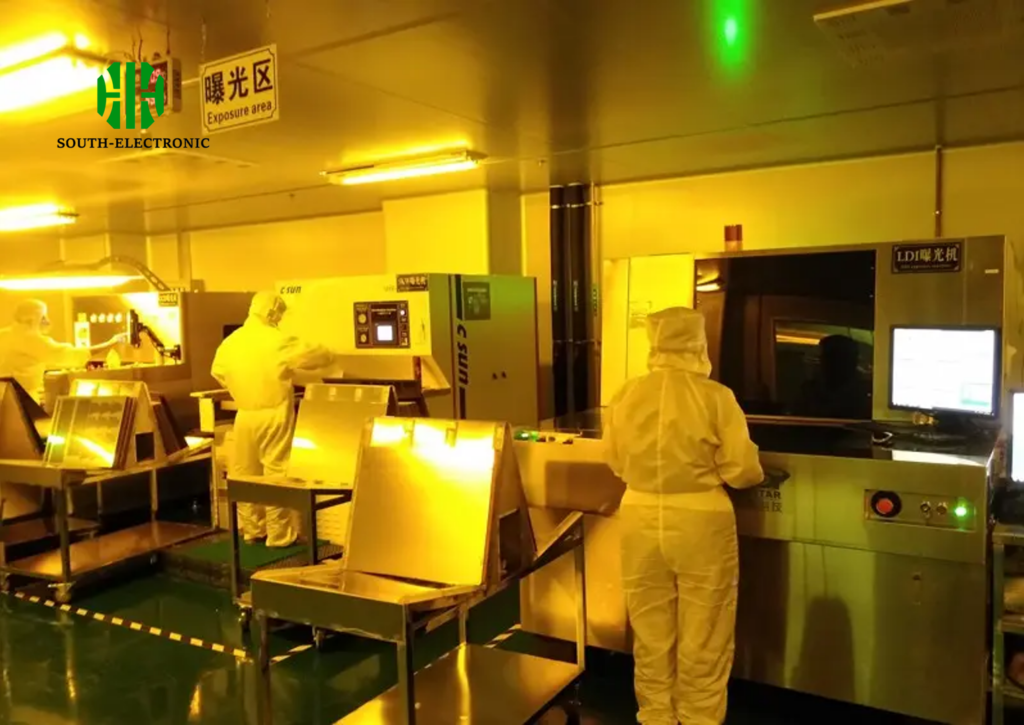
Production lines for regular PCBs crisscross like highway interchanges. Transparent board manufacturing resembles a delicate dance requiring precision lighting and dust-free environments.
Transparent PCB fabrication replaces copper cladding with sputtered conductive layers. Laser etching becomes critical for maintaining clarity, while component mounting uses specialized optically clear adhesives (OCAs)[^3].
Step Comparison Table
| Traditional PCB Step | Transparent PCB Adaptation | Reason |
|---|---|---|
| Copper lamination | ITO sputtering | Maintains transparency |
| Chemical etching | Laser ablation | Preserves conductive traces |
| Solder paste screen | OCA dispenser | Avoids opaque solder |
Last year, I watched a factory batch fail because dust particles created micro-cracks during lamination. Transparent PCB makers use clean rooms rated ISO Class 5—higher than surgical theaters—to prevent such disasters. Component placement shifts from wave soldering to precision robotic arms applying UV-cured adhesives.
What Are the Key Advantages and Limitations of Transparent PCBs?
Frosted PCB surfaces conceal messy circuits. Transparent boards flaunt their engineering, merging form with function—until material limits strike back.
Transparent PCBs enable see-through electronics and creative industrial designs. However, they carry higher production costs, reduced thermal tolerance, and complex repair challenges compared to standard boards.
![]()
Pros vs Cons Analysis
| Advantages | Limitations | Mitigation Strategies |
|---|---|---|
| Aesthetic flexibility | 30-40% higher cost | Target premium products |
| Light-guiding features | Max operating temp: 110°C | Active cooling systems |
| UV resistance | Difficult trace repairs | Redundant circuit design |
During a wearable tech project, my team struggled with heat dissipation in transparent boards. We solved it by embedding microfluidic cooling channels—proving that innovation can overcome these materials’ ceiling. But budget-minded startups often balk at the 3x price jump over FR-4 boards.
Which Industries Benefit Most from Transparent PCB Technology?
Transparent circuits aren’t just for tech showoffs. Multiple sectors now demand electronics that can vanish into their surroundings without sacrificing performance.
Medical imaging, premium retail displays, next-gen automotive HUDs[^4], and augmented reality gear all utilize transparent PCBs. Their light-transmissive nature enables innovations from heads-up windshields to X-ray visible surgical tools.
![]()
Adoption Rate Analysis
| Industry | Adoption Stage | Key Driver | Use Case Example |
|---|---|---|---|
| Consumer Electronics | Early mainstream | Design differentiation | See-through smartphone accents |
| Automotive | Pilot projects | HUD advancements | Windshield-integrated speed displays |
| Medical | Niche adoption | Radiation transparency | MRI-compatible monitoring kits |
| Aerospace | R&D phase | Weight reduction | Cockpit panel integrations |
I recently consulted on museum display cases using transparent PCs to power hidden interactive elements. Visitors trigger infrared sensors through the glass without seeing any buttons—the ultimate invisible interface solution. Defense contractors also show interest for augmented reality visors, but material strength concerns linger.
Conclusion
Transparent PCBs merge engineering with artistry, enabling electronics that dazzle and disappear. While cost and complexity hinder mass adoption, their unique benefits ensure growing roles in medical, automotive, and consumer tech frontiers.
[^1]: Learn about polyimide films, their properties, and why they are essential in flexible electronics by visiting this resource.
[^2]: Discover the significance of ITO in transparent electronics and its role in enhancing device performance by checking this link.
[^3]: Learn about OCAs and their crucial role in transparent PCB manufacturing, which can improve your product designs.
[^4]: Learn about the latest innovations in automotive HUDs that improve safety and user experience through transparent PCBs.

