
Engineers, designers, and manufacturers need reliable circuit board materials. Cheap options fail under heat; exotic materials inflate costs. FR4 PCB delivers flame resistance, thermal stability, and affordability—making it the bedrock of modern electronics. Let’s dissect why it dominates 80% of PCB applications.
FR4 PCB[^1] is a composite of fire-retardant epoxy resin and woven fiberglass, offering high mechanical strength, thermal resistance (Tg 130-180°C), and electrical insulation. Its cost-effectiveness and versatility make it ideal for consumer tech, industrial systems, and medical devices.
Understanding FR4’s strengths—and limitations—is key to optimizing your designs. Below, we break down its composition, advantages, and quality checks to ensure you harness its full potential.
FR4 PCB Core Definition?
Confused by terms like "FR4 substrate" or "dielectric core"? Cutting through jargon: FR4 isn’t just "plastic with fiber"—it’s a refined solution balancing safety, performance, and scalability for PCB manufacturing.
The FR4 core is a fiberglass-reinforced epoxy laminate[^2] serving as the structural base for PCBs. Its flame-retardant properties[^3] (UL94 V-0 rated) and glass transition temperatures (Tg) up to 180°C prevent warping and delamination under thermal stress.
Why Does FR4 Structure Matter?
FR4’s layered design ensures stability across environments:
| Layer | Role |
|---|---|
| Epoxy Resin | Binds materials, provides insulation |
| Woven Fiberglass | Enhances mechanical rigidity |
| Copper Foil | Conducts signals/power |
Thermal Resilience[^4]:
- Standard FR4: Tg 130-140°C (e.g., consumer electronics).
- High-Tg FR4: Tg ≥170°C (e.g., automotive/industrial).
Key Design Impact: Lower Tg materials (<130°C) risk deformation during soldering, causing microcracks. Always verify Tg ratings for your application’s thermal profile.
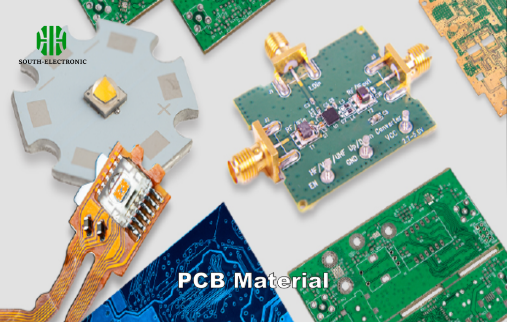
Breaking Down FR4 Material Composition?
PCB performance hinges on material science. FR4’s magic lies in its precise epoxy-fiber ratio, but what’s inside directly dictates your board’s thermal, mechanical, and electrical behavior.
FR4 comprises 60-70% woven fiberglass[^5] (SiO₂) for strength and 30-40% brominated epoxy resin for flame resistance. Fillers like alumina improve thermal conductivity, while antimony oxide enhances fire retardancy.
Decoding Component Ratios
- Fiberglass Weave Density:
- 1080 (low): Flexible, low-cost.
- 2116 (mid): Balanced strength/flex.
- 7628 (high): Rigid, for heavy components.
Additives Matter:
- Bromine[^6]: Provides UL94 V-0 flame resistance.
- Silane Coupling Agents: Boost resin-fiberglass adhesion.
Trade-offs:
- Higher resin content = better moisture resistance but lower dimensional stability.
- Thicker fiberglass = higher CTI (Comparative Tracking Index) for high-voltage apps.
Key Advantages That Make FR4 Dominant in PCB Market?
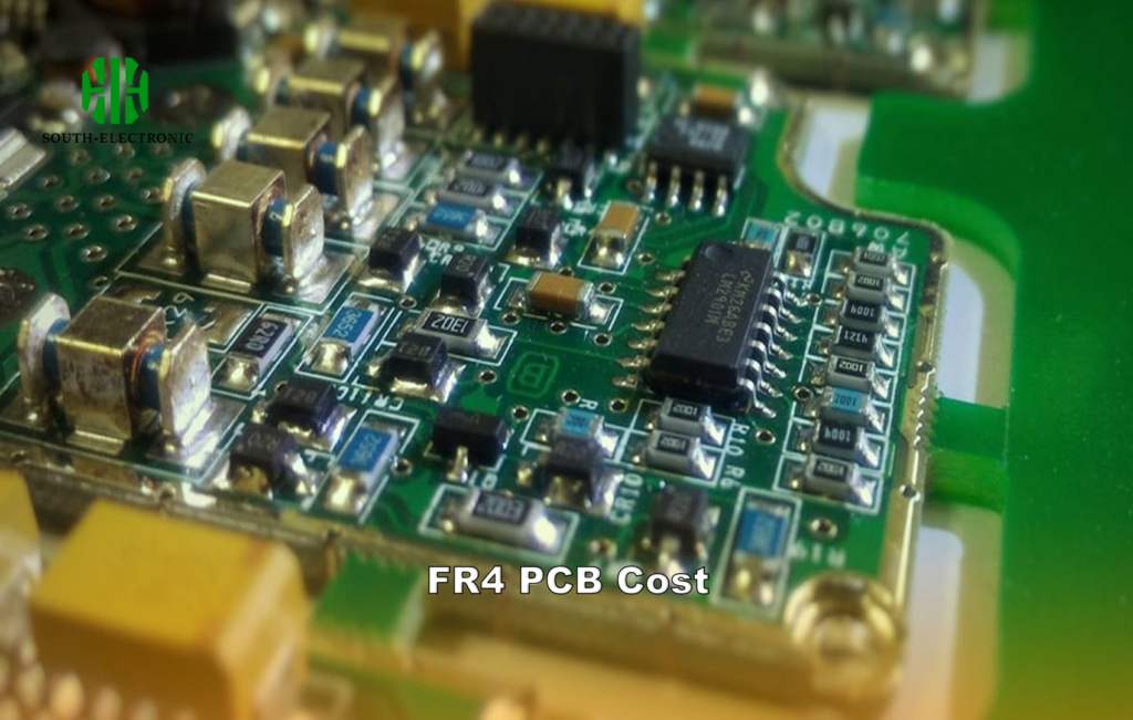
Why does FR4 outsell ceramics, PTFE, and metals 5:1? From cost to compliance, its balanced properties eliminate compromises for most applications.
FR4 dominates due to its low cost[^7] ($2-$10/sq.ft), ease of fabrication, and compliance with RoHS/UL standards. Its dielectric constant[^8] (4.3-4.9 @1MHz) suits analog/digital circuits, while halogen-free variants[^9] meet eco-regulations.
FR4 vs. Alternatives
| Material | Cost | Dielectric Loss | Tg Range | Best For |
|---|---|---|---|---|
| FR4 | $ | Moderate | 130-180°C | General-purpose |
| Rogers | $$$$ | Low | 280°C | RF/mmWave |
| Aluminum | $$ | N/A | N/A | High-power LED |
| PTFE | $$$ | Very Low | 160°C | Aerospace radar |
Cost Driver: FR4 uses standard subtractive etching, while Rogers requires specialized laser drilling. For sub-6GHz designs, FR4’s loss tangent (10GHz RF circuits due to high dielectric loss (Df ≈0.02). Similarly, extreme thermal (>200°C) or flex applications require ceramics, polyimide, or PTFE substrates.**
Scenarios Demanding Alternatives
-
High-Frequency (mmWave):
- FR4’s Df increases with frequency, causing signal degradation.
- Switch to Rogers 4350B (Df 0.0037 @10GHz).
-
Thermal Cycling:
- Repeated 150°C+ cycles fatigue FR4; Alumina ceramics handle 300°C.
-
High Voltage:
- FR4’s CTI is ~200V; Polyimide (CTI 600V) resists conductive anodic filaments.
How to Verify FR4 Quality?
Not all FR4 is equal. Counterfeit or subpar laminates cause delamination, CAF growth, and premature failures. Rigorous verification ensures reliability.
Validate FR4 via IPC-4101 certs[^10], Tg testing (DSC/TMA), and CAF resistance checks[^11]. Use cross-section microscopy[^12] to inspect fiberglass-resin bonding and copper peel strength (>8lb/in).

Quality Assurance Checklist
| Test | Method | Pass Criteria |
|---|---|---|
| Tg Measurement | DSC/TMA | ±5°C of spec |
| Peel Strength | IPC-TM-650 2.4.8 | >8lb/in for 1oz Cu |
| CAF Resistance | IPC-650 2.6.25 | No growth at 85°C/85%RH |
| Dielectric Constant | ASTM D150 | 4.3-4.9 @1MHz |
Red Flags:
- Discoloration (overcured resin).
- Voids in fiberglass weave (poor impregnation).
- Tg below datasheet (underpolymerization).
Conclusion
FR4 PCB remains the go-to for balancing cost, performance, and manufacturability. While unsuitable for extreme conditions, its adaptability across consumer, industrial, and medical sectors cements its dominance—as long as designers validate quality and match specs to application needs.
[^1]: Explore the advantages of FR4 PCB to understand why it’s the preferred choice in electronics, ensuring reliability and performance.
[^2]: Discover the significance of fiberglass-reinforced epoxy laminate in PCB manufacturing and its impact on performance and reliability.
[^3]: Learn about flame-retardant properties and their critical role in ensuring safety and durability in PCB applications.
[^4]: Understanding Thermal Resilience is crucial for ensuring the reliability and performance of PCBs in various applications. Explore this link to deepen your knowledge.
[^5]: Discover the intricate composition of FR4 material to understand its impact on PCB performance and reliability. This knowledge is essential for effective design.
[^6]: Learn how Bromine contributes to flame resistance in materials, which is vital for safety in electronic applications. This resource will provide valuable insights.
[^7]: Exploring this resource will provide insights into how low-cost materials like FR4 can enhance PCB production efficiency and affordability.
[^8]: Understanding dielectric constant is crucial for optimizing PCB designs, and this link will deepen your knowledge on its impact on performance.
[^9]: Discover the environmental benefits and compliance advantages of halogen-free materials, which are increasingly important in modern PCB manufacturing.
[^10]: Understanding IPC-4101 certifications can help ensure the quality and reliability of FR4 materials in your projects.
[^11]: Exploring CAF resistance checks will provide insights into preventing failures in FR4 laminates, crucial for long-term performance.
[^12]: Learning about cross-section microscopy can enhance your understanding of material integrity and bonding in FR4 laminates.

