
Power outages cripple electronics, solar systems go silent, and industrial machines freeze – all caused by poor AC power conversion. The invisible hero solving these crises? The silent powerhouse called inverter circuit board[^1].
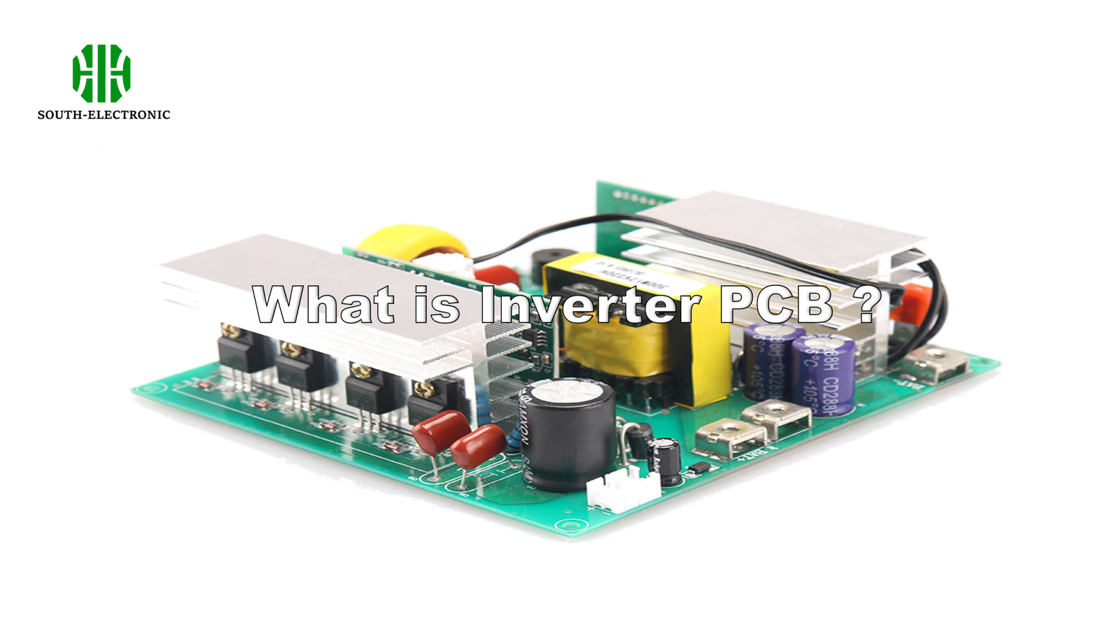
An inverter circuit board converts DC power (like batteries) into stable AC electricity using transistors, transformers, and high-frequency switches. It enables renewable energy systems, uninterrupted power supplies, and precision industrial operations.
)
Let’s dissect how this unassuming board achieves energy alchemy – from its critical components to real-world applications. You’ll discover why engineers call it the "electricity shape-shifter."
Core Components of an Inverter Circuit Board
Ever wondered why some inverters fail during voltage spikes while others thrive? The answer lies in 4 non-negotiable components that form the board’s DNA.
The core components are power transistors[^2] (IGBTs/MOSFETs), transformers, capacitors, and PWM controller[^3]s, working together to regulate and convert electricity with millisecond precision.
)
The Hardware Orchestra
Here’s how each component contributes to power conversion:
| Component | Role | Failure Impact | Common Types |
|---|---|---|---|
| Power Transistors | High-speed DC switching | Overheating/Burned board | IGBT, MOSFET, GaN |
| Transformers | Voltage boosting/reduction | Inefficient conversion | Toroidal, Laminated |
| Filter Capacitors | Smooth output waveform | Signal distortion | Electrolytic, Ceramic |
| PWM Controller | Switching timing control | Frequency instability | Microcontroller-based |
I once debugged a solar inverter that kept frying transistors – the culprit was undersized heat sinks causing thermal runaway. This nightmare teaches us: Component quality determines system lifespan. Modern boards now use GaN transistors handling 100kHz+ switches with 98% efficiency, compared to traditional 70kHz MOSFETs.
How Inverter Circuit Boards Work
What if your "DC to AC" converter creates chaotic electricity damaging devices? Mastering switching frequency and waveform control separates pro-grade boards from cheap knockoffs.
Inverter boards rapidly switch DC current using transistors controlled by PWM signals, creating stepped AC waves refined by filters into smooth sine outputs matching grid standards.
)
The Physics of Switching
1️⃣ DC Switching Stage
IGBTs toggle 3,000-20,000 times/second, creating pulsed DC. Higher frequencies enable smaller transformers but increase heat.
2️⃣ Voltage Transformation
Pulsed DC enters laminated/ferrite core transformers for voltage adjustment. 12V DC → 170V peak AC is typical for home inverters.
3️⃣ Wave Shaping
LC filters convert stepped/square waves into pure sine waves. Total Harmonic Distortion (THD)[^4] below 3% is mandatory for medical/sensitive equipment.
4️⃣ Feedback Regulation
Current sensors and MCUs adjust PWM duty cycles in real-time. Without this, a 10% load drop could melt your microwave’s circuitry.
Key Applications of Inverter Circuit Boards
Why pay $5,000+ for industrial inverters when $50 models exist? Application demands dictate board complexity – here’s where engineering meets real-world needs.
Primary applications include solar/wind energy systems (60% market share), industrial motor drives (VFDs), UPS backups, and EV charging stations requiring precise voltage/frequency control.
)
Sector-Specific Solutions
| Industry | Requirement | Board Features |
|---|---|---|
| Renewable Energy | Maximum Power Point Tracking[^5] | Advanced DSP controllers |
| Data Centers | Zero-transfer time | Dual-conversion topology |
| EVs | Bidirectional charging | SiC semiconductors |
| HVAC | Variable speed control | Sensorless vector drives |
During a hospital UPS installation, we used inverters with 90%), waveform type (pure sine), and protection features (overload/short-circuit).**
)
The Engineering Checklist
-
Voltage Compatibility
- 12V/24V/48V DC inputs for automotive vs 200-800V in industrial
- Wide-input designs (90-305VAC) for unstable grids
-
Efficiency Curves
- Peak 95% at 50-70% load
- Avoid boards dipping below 80% at full load
-
Protection Hierarchy
- Layer 1: Fuses/Circuit breakers
- Layer 2: Digital current limiting
- Layer 3: Thermal shutdown
-
Certification Marks
- UL 1741 for grid-tie systems
- IP65 waterproofing for outdoor use
-
Interface Needs
- RS485/Modbus for industrial automation
- WiFi monitoring in smart homes
Conclusion
Inverter circuit boards transform raw DC into precision AC power – the silent enablers of renewable energy, industrial automation, and mission-critical power backups. Choose with specs matching your operational reality.
[^1]: Explore this link to understand the fundamental role of inverter circuit boards in energy conversion and their applications in renewable energy.
[^2]: Learn about power transistors, their types, and how they impact the efficiency and reliability of inverter circuits.
[^3]: Discover the significance of PWM controllers in regulating power conversion and ensuring stable output in electronic systems.
[^4]: Learn about THD to ensure your inverter meets quality standards for sensitive equipment, enhancing performance and reliability.
[^5]: Explore Maximum Power Point Tracking to optimize energy harvest in solar and wind systems, maximizing efficiency and output.

