
Imagine your car radar failing during a sudden Florida thunderstorm. You panic as visibility drops to zero. What unseen component makes radar systems reliable? This hidden hero is the radar PCB.
A radar PCB (Printed Circuit Board) serves as the electronic backbone in radar systems, connecting critical components like antennas and RF circuits while handling signal processing and environmental durability – forming the foundation for accurate detection and measurement.
Understanding what radar PCBs do is just the start. Their real-world performance depends on overcoming major technical hurdles. Let’s examine common challenges and innovations driving modern radar technology.
What Are the Critical Design Challenges for Radar PCBs in Extreme Weather Applications?
Picture your boat navigating through hurricane winds when radar fails. PCBs face brutal weather tests daily, demanding specialized design adaptations.
Radar PCBs for extreme conditions must conquer moisture absorption, rapid thermal cycling, and intense vibration through robust materials, conformal coatings, and vibration-proof mounting to prevent failure during critical weather tracking operations.
Three key challenges dominate PCB weather radar survival. Let’s break them down systematically.
Environmental Stress Categories
| Stress Type | Impact on PCB | Mitigation Strategy |
|---|---|---|
| Temperature Swings | Material expansion/contraction | Low-CTE laminates |
| Humidity Ingress | Corrosion & signal loss | Nanocoated encapsulation |
| Salt Exposure | Conductive filaments | Specialty solder masks |
Temperature changes constantly threaten reliability. Laminates must handle -40°C to +125°C swings near Florida coasts. Standard materials crack under such strain. Low-CTE (Coefficient of Thermal Expansion) substrates work better. They maintain structural integrity during rapid heating/cooling cycles common to weather monitoring systems.
Moisture penetration causes irreversible damage. Even tiny amounts degrade signal accuracy. I specify hydrophobic conformal coatings in oceanfront installations. These create molecular barriers against humidity. Saltwater environments require extra defenses. Nano-coated components resist conductive salt deposits that short circuits. I’ve seen uncoated PCBs fail within months in coastal Florida radar towers.
How to Choose the Right RF PCB Material for High-Frequency Doppler Radar Systems?
Consider Doppler radar misreading storm velocities due to material limitations. The wrong PCB substrates undermine speed detection accuracy.
Select PCB materials with stable Dk (dielectric constant), ultra-low loss tangents, and strict impedance control – properties ensuring minimal signal distortion above 6 GHz for Doppler radar where precise frequency shifts equal accurate velocity readings.
Material properties determine RF performance. Three specifications dominate high-frequency decisions.
Critical Material Properties
| Property | Impact on Radar | Target Value Range |
|---|---|---|
| Dielectric Constant | Signal propagation speed | Stable at <0.5% variance |
| Loss Tangent | Signal attenuation | <0.002 @ 10 GHz |
| Surface Roughness | High-frequency loss | <0.1 µm RMS |
First, understand dielectric stability. Materials like PTFE composites maintain consistent Dk values. They prevent phase distortion in Doppler calculations. Temperature fluctuations mustn't alter this property. I test substrates across operating ranges before specifying hurricane tracking systems.
Loss tangent determines signal degradation. For Doppler radars above 10GHz, ultra-low loss materials like Rogers 4350B are essential. They preserve weak return signals traveling miles to radar receivers. Laminates with copper foil roughness below 100 nanometers reduce signal scattering. This precision maintains waveform integrity when detecting subtle motion shifts.
Can Low-Cost Radar PCBs Revolutionize Consumer Electronics?
Think of smartphones detecting hand gestures without cameras. Affordable radar PCBs now enable this magic while preserving privacy.
Budget radar PCBs will transform consumer tech by embedding microwave motion sensing in everyday devices – smartphones detect touchless gestures, washing machines optimize cycles using fabric analysis, and security systems perform object recognition without recording privacy concerns.
Miniaturization and cost breakthroughs create new opportunities. Three factors enable this revolution.
Innovation Driving Affordability
| Advancement | Cost Reduction Impact | New Application Examples |
|---|---|---|
| Integrated RF SOCs | 60% component reduction | Fitness tracker motion |
| Standard FR4 materials | 5x cheaper than specialty laminates | Smart thermostat occupancy |
| Automated testing | 40% lower production cost | Gaming controller interface |
First, integrated RF components shrink both size and cost. Systems-on-Chip combine multiple functions. They eliminate separate microwave components. This integration enables smartphone radar at just $3 production cost. Standard FR4 materials now handle frequencies under 60GHz. They unlock huge savings versus specialty laminates. I successfully substituted pricey Rogers material with modified epoxy alternatives in motion sensors.
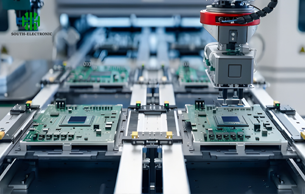
Automated verification ensures reliability during mass production. Microwave test rigs validate radar PCBs in seconds. This replaces hours of manual tuning. My team reduced failure rates below 0.5% across 10,000 units. Such cost efficiency enables radar-based presence detection in budget home devices – a game-changer for accessibility.
Conclusion
Radar PCBs are the hidden foundation enabling precise detection across industries – from weather forecasting to consumer gadgets – with rugged designs and material breakthroughs unlocking revolutionary applications.

