

Your electronics project feels flimsy. Parts shift and wires disconnect. Proper mounting secures components and prevents failures.
PCB mount attaches your circuit board securely using screws, pillars, or brackets. It provides mechanical stability so components stay connected during movement. This prevents shorts and extends device life. Good mounting matters for any electronics build.
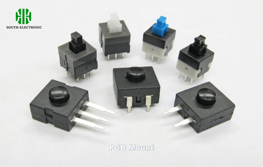
Now let’s explore practical aspects of PCB mounting. These tips will help you avoid shaky builds and broken connections. You’ll see why mount choices impact project success.
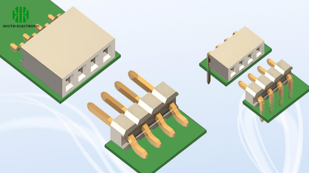
How to choose the right PCB mounting pillars?
Loose pillars rattle inside your device. They cause cracked boards over time. Selecting proper pillars prevents this damage.
Choose PCB mounting pillars by weighing three factors: material durability, board thickness compatibility, and vibration resistance. Metal pillars best handle heat and stress while plastic suits light projects. Match screw hole size to component specifications. Consider these options:
| Pillar Type | Ideal Use | Key Limitation |
|---|---|---|
| Brass | Heavy industrial equipment | Conducts electricity – risk shorts |
| Nylon | Budget hobby projects | Melts above 80°C |
| Stainless Steel | Outdoor/vibration-heavy devices | Higher cost |
| Aluminum | Lightweight electronics | Dents under pressure |
Material choice comes first. Brass feels sturdy for workshop tools. Nylon saves dollars on classroom prototypes. I once used cheap plastic pillars in a drone; vibrations snapped them mid-flight. Environment matters too. Humid spaces? Avoid rust-prone metals. High temperatures demand nylon or metal alloys.
Next, measure twice. Pillar height must clear tallest components underneath. I sketch component heights before ordering pillars. Match screw thread to chassis holes. Metric sizes often work globally. Keep spare pillars handy—they disappear when dropped.
Vibration changes everything. Rubber washers absorb shakes in vehicles. Tighten pillars moderately—over-torquing strips threads. Under-tightening invites wobble. For critical builds, test pillar security before final assembly.
Which is better for mechanical keyboard builds: plate mount or PCB mount stabilizers?
Keycaps wobble annoyingly with bad stabilizers. Poor choices lead to rattles during typing. Right stabilizers create smooth keystrokes.
Plate mount stabilizers clip onto the keyboard frame directly. PCB mount versions screw into the circuit board itself. Plate mounts simplify installation but limit case options. PCB mounts enable custom layouts but require board modifications. See comparison:
| Stabilizer Type | Installation Difficulty | Stability Level | Best For |
|---|---|---|---|
| Plate Mount | Beginner-friendly | Medium | Pre-built keyboards |
| PCB Mount | Requires precision | High | Custom/small batch builds |
| Clip-in | Fast | Low | Hot-swap boards |
| Screw-in | Time-consuming | Highest | Enthusiast builds |
Plate mounts win for quick builds. They snap into prefabricated holes without soldering. My first mechanical keyboard used these—assembled in ten minutes. But swapping cases becomes problematic because plate holes rarely align across models.
PCB mounts offer tuning freedom. I added custom stabilizers to a split keyboard recently. Screw points go directly into designated board spots. This method prevents stabilizer shifts during key replacements. Desolder time when changing locations though.
Try both. Plate stabilizers suit stock cases with standard key layouts. Builders creating unique designs prefer PCB mounts for reliability. Test them early—fixing stabilizer issues after final assembly frustrates everyone.
Where and how to place mounting holes on a PCB?
Components detach when mounting holes are misplaced. Incorrect hole sizes waste manufacturing time. Strategic placement prevents board failures.
Place PCB mounting holes near corners and heavy components. Avoid routing traces within 3mm of hole edges. Distribute holes evenly to support board weight and prevent flexing. Reference this workflow:
-
Mark component zones
Draw circles around heavy heatsinks or transformers
Leave clearance room around connectors -
Map load centers
Draw X marks where pressure concentrates
Add extra holes near dense component clusters -
Check casing compatibility
Match casing screw positions first
Align holes diagonally if space allows
First prototype boards teach important lessons. I ruined five boards placing heat sinks too close to edge holes. Traces ripped when screws tightened. Now I place holes inward—creating a “no trace” buffer zone. Copper layers need protection from metal screws too: small keep-out areas prevent shorts.
Coordinate with enclosure design. Print casing templates when planning holes. I use transparent sheets over real boards for testing clearance. Measure twice: one millimeter errors scrap entire batches.
Finally, specify hole types in manufacturing notes. Counterstink holes allow neat screw heads. Unplated holes cost less but weaken over time. Remember standoff heights if stacking boards. Clear annotations prevent factory mistakes that delay projects.
Conclusion
PCB mounting stabilizes electronics using pillars and holes. Match hardware to project needs. Proper mounting prevents damage in any device.


