
Choosing PCB materials for GHz-range circuits? Signal distortion plagues many designers, ruining device performance and reliability. I faced this frustration myself when early prototypes failed tests.
No single "best" material exists, but Rogers, Isola, or Panasonic laminates typically outperform FR-4 for high-frequency PCBs. Their low dielectric constant (Dk), minimal dissipation factor (Df), and smooth copper surfaces preserve signal integrity better than standard materials at microwave frequencies.
Understanding material differences changes everything. Keep reading to decode key criteria for your RF projects.
Now, let’s tackle common high-frequency PCB challenges step by step.
What is the difference between high speed and high-frequency PCBs?
Signal degradation panic hits when design specs blur these concepts. Confusing them risks costly board respins.
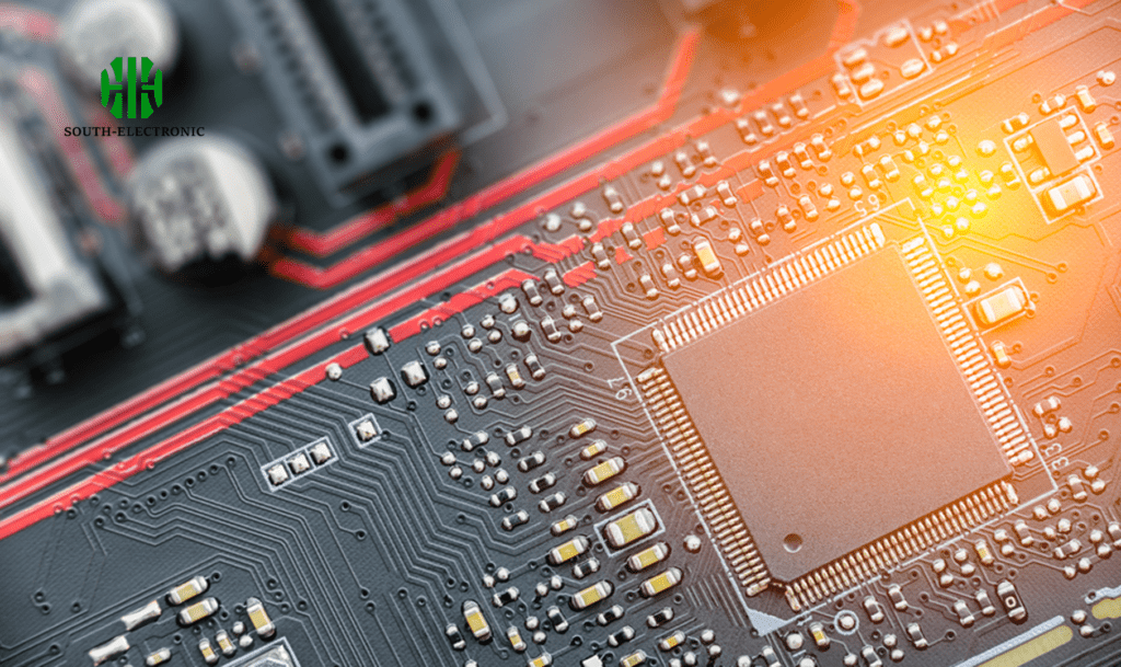
High-speed PCBs handle fast digital signal edges (nanosecond transitions) needing impedance control. High-frequency PCBs manage electromagnetic waves above 1GHz requiring material stability against frequency shifts. Digital designs focus on timing; RF designs fight signal loss.
Breaking Down the Core Distinctions
While both deal with signal integrity, their failure modes differ vastly. I categorize them by three conflict zones:
| Conflict Zone | High-Speed PCB Pain | High-Frequency PCB Nightmare | |
|---|---|---|---|
| Critical Parameter | Rise time control (e.g., 0.003 (@10GHz) | Rogers RT/duroid 5880 (Df=0.0009) | 40° cooler runtime |
| Radiation Loss | Unshielded microstrip | Coplanar waveguide with ground vias | 23dB isolation |
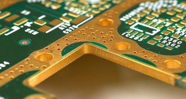
Dielectric absorption melted my first 60GHz sensor. Megtron 6’s Df of 0.002 cut losses better than FR-4’s 0.02. I reduce solder mask over RF traces – its uneven Dk creates impedance bumps. Via fences around antenna feedlines suppressed stray coupling. Humidity kills too; hydrophobic PTFE cores in Isola I-Tera kept my marine radars stable.
Which High Frequency PCB Surface Finish Wins for RF Applications?
Solder finish chaos causes impedance spikes. I recall a 18GHz filter failing QA due to ENIG nickel diffusion.
Electroless Nickel Immersion Gold (ENIG) provides flat surfaces best for RF traces. Hard gold beats HASL for insertion loss but costs 3x. Immersion silver suits budget projects under 6GHz where tarnishing risks are low.
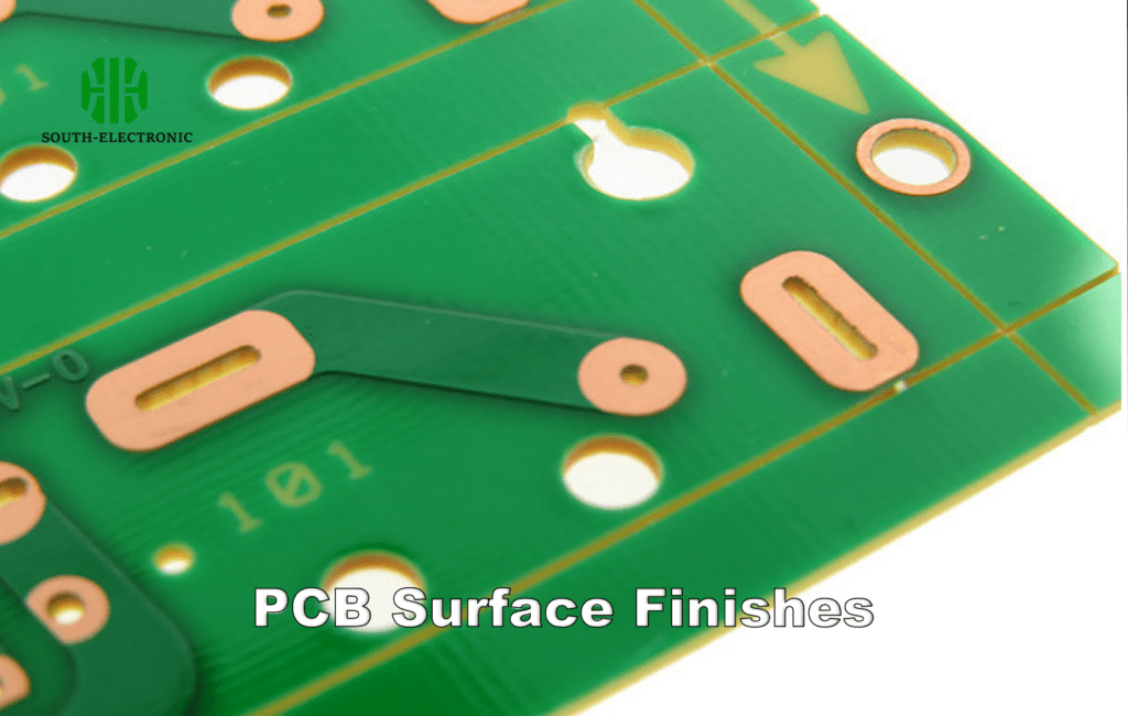
Surface Finish Performance Faceoff
Nickel layers distort high-frequency signals. When my client insisted on ENEPIG, their VSWR hit 1.8 at Ku-band. Here’s how common finishes compare:
| Finish Type | Thickness Impact | Best Use Case | My RF Warning |
|---|---|---|---|
| ENIG | 3-6μm Ni causes resonance | 70μin ruins GHz Q-factor | |
| Immersion Sn | Tin whiskers beyond 10°C swing | Low-cost narrow band | Drops 18% S21 at 15GHz over aging |
| OSP | Thickness variability ±20% | Consumer WiFi gear | Avoid phase-sensitive phased arrays |
| Hard Au | Consistent 0.05-0.2μm Au | Aerospace repeaters | Skip ENEPIG’s extra Pd layer! |
I always test finish roughness with atomic force microscopy. Silver migration killed a drone telemetry kit stored near ozone. ENIG won my automotive radar project – its gold surface maintains repeatable solderability. For 77GHz radars, direct bond copper techniques work better than any solderable finish.
Conclusion
Choose PCB materials based on specific frequency/bandwidth needs. Rogers, Isola, or Panasonic laminates minimize high-frequency losses best when paired with RF-optimized finishes.


