
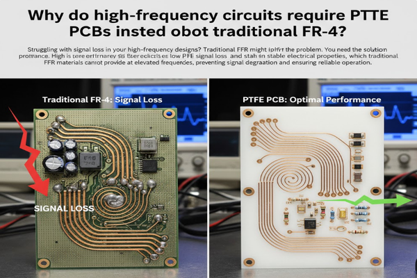
Struggling with signal loss in your high-frequency designs? Traditional FR-4 might be the problem. You need a better solution for optimal performance.
High-frequency circuits rely on PTFE PCBs1 due to their extremely low signal loss2 and stable electrical properties, which traditional FR-43 materials cannot provide at elevated frequencies, preventing signal degradation4 and ensuring reliable operation.
Have you ever wondered why some electronic circuits demand specialized materials? It turns out that for applications involving very fast signals, the choice of circuit board material makes all the difference. Let's explore why.
What is the difference between FR4 and PTFE?
Facing signal issues at high frequencies? The material you choose for your PCB directly impacts performance. Understand the core differences now.
FR-4 is a common PCB material made of woven fiberglass and epoxy resin, good for general electronics, while PTFE (Polytetrafluoroethylene), like Teflon, is a high-performance plastic known for its very low dielectric loss, making it ideal for high-frequency applications5.
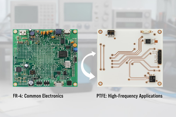
When we talk about PCBs, the base material is crucial. FR-4 is a standard choice, known for its cost-effectiveness and good mechanical strength. However, its electrical properties change significantly as frequencies climb. PTFE, on the other hand, is specifically engineered for high-frequency environments. I've seen engineers struggle with FR-4 in RF designs6, only to find immediate improvements by switching to PTFE. The dielectric constant of FR-4 can vary, and its loss tangent increases dramatically at high frequencies, leading to signal attenuation. PTFE's dielectric constant is more stable across a wide frequency range, and its loss tangent is significantly lower.
Material Composition
| Feature | FR-4 | PTFE |
|---|---|---|
| Composition | Woven fiberglass, epoxy resin | Fluoropolymer (e.g., Teflon), ceramic filler |
| Structure | Laminated, rigid | Flexible or rigid, often ceramic-filled |
| Cost | Lower | Higher |
Electrical Performance at High Frequencies
| Metric | FR-4 (Typical @ GHz) | PTFE (Typical @ GHz) |
|---|---|---|
| Dielectric Const. | 4.2-4.8 | 2.2-3.5 |
| Loss Tangent | 0.018-0.025 | 0.0009-0.002 |
| Signal Loss | High | Very Low |
Which type of PCB is commonly used in high frequency applications?
Concerned about performance in your high-frequency project? Selecting the right PCB material is critical. Discover the industry standard.
PTFE-based PCBs, often branded as Rogers, are commonly used in high-frequency applications because their superior electrical properties, including low dielectric loss and stable dielectric constant, minimize signal degradation at RF and microwave frequencies.
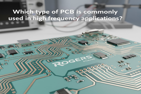
For anyone working with signals in the hundreds of MHz or GHz range, the choice is clear: PTFE is the go-to material. My own experience in designing RF modules has repeatedly shown that neglecting material properties leads to system failure. The reasons for this preference are rooted in fundamental physics. When a signal travels through a PCB, part of its energy is lost to the dielectric material. This loss increases with frequency. FR-4’s molecular structure7 causes more energy absorption, manifesting as heat and signal attenuation. PTFE's molecular structure, being non-polar, absorbs very little energy, preserving signal integrity. This makes it indispensable for applications like 5G infrastructure8, satellite communication9, and radar systems10.
Why PTFE Excels
- Low Dielectric Loss: Minimizes signal energy conversion to heat.
- Stable Dielectric Constant: Ensures consistent signal propagation speed.
- Low Moisture Absorption: Maintains electrical properties in various environments.
- Excellent Thermal Stability: Performs reliably over a wide temperature range.
Common High-Frequency Applications
- Wireless Infrastructure: 5G base stations, antennas.
- Aerospace & Defense: Radar systems, satellite communication.
- Automotive: ADAS sensors, autonomous driving.
- Medical: High-resolution imaging.
What is the difference between PCB and FR4?
Confused about PCB terminology? Understanding the basics helps. Learn how FR4 relates to the broader concept of a PCB.
A PCB (Printed Circuit Board) is a general term for a board that electronically connects components using conductive pathways, while FR-4 is a specific, common type of material used to construct many PCBs, known for its fiberglass and epoxy composition.
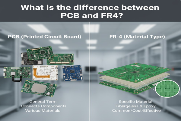
This is a common point of confusion. Think of it this way: a PCB is the overall component – the green board with traces that your electronic parts sit on. FR-4 is simply one of many materials that a PCB can be made from. It's like saying "car" versus "steel." A car is made of many materials, and steel is one common material used in cars. FR-4 stands for "Flame Retardant 4," indicating a standard for material properties related to fire resistance and electrical characteristics. Most consumer electronics use FR-4 PCBs because it’s a good balance of cost, performance, and manufacturability for lower frequencies.
PCB: The General Concept
- Definition: A board that mechanically supports and electrically connects electronic components.
- Components: Substrate, copper traces, solder mask, silkscreen.
- Function: Enables complex electronic circuits in a compact form.
FR-4: A Specific Material
- Definition: A specific grade of fiberglass-reinforced epoxy laminate material.
- Characteristics: Good mechanical strength, electrical insulation, cost-effective.
- Usage: Widely used for general-purpose electronic PCBs, especially at lower frequencies.
Types of PCB Materials Beyond FR-4
| Material Type | Key Characteristic | Typical Application |
|---|---|---|
| FR-4 | Cost-effective, general purpose | Consumer electronics, digital circuits |
| PTFE (Rogers) | Low loss, stable dielectric | RF/Microwave, high-speed digital |
| Polyimide | Flexible, high temperature | Flexible circuits, medical devices |
| Ceramic | High thermal conductivity, stable | High-power LEDs, sensors |
What are high frequency PCBs?
Dealing with fast signals and signal integrity challenges? High-frequency PCBs are engineered to overcome these hurdles.
High-frequency PCBs are specialized circuit boards made from advanced materials like PTFE, designed to handle signals operating at hundreds of MHz to several GHz with minimal loss, distortion, and impedance mismatch, ensuring signal integrity in demanding applications.
When I first started working with RF systems, I quickly learned that not all PCBs are created equal. A "high-frequency PCB" isn't just any board; it's a board carefully constructed with specific materials and design rules to preserve the integrity of very fast signals. Imagine trying to talk through a long, leaky hose – that's what happens to high-frequency signals on the wrong material. High-frequency PCBs use materials that have a very low dielectric constant and a very low loss tangent. This means the signal experiences less resistance and less energy absorption as it travels through the board. The material also needs to have a consistent dielectric constant across the board and over temperature, to prevent phase shifts and impedance variations that could distort the signal.
Key Characteristics of High-Frequency PCBs
- Low Loss Tangent (Df): Minimizes signal attenuation.
- Stable Dielectric Constant (Dk): Ensures predictable signal speed and impedance.
- Controlled Impedance: Critical for matching signal lines to components.
- Low Moisture Absorption: Prevents Dk shifts due to humidity.
- Excellent Thermal Performance: Maintains stability in varying operating temperatures.
Design Considerations for High-Frequency PCBs
| Aspect | Importance | Impact if Neglected |
|---|---|---|
| Material Selection | Dominant factor for signal loss and Dk | Signal attenuation, phase distortion |
| Trace Geometry | Controls impedance, reduces reflections | Impedance mismatch, signal reflections |
| Ground Planes | Provides stable reference, reduces EMI | Increased noise, cross-talk |
| Via Design | Minimizes parasitic inductance/capacitance | Signal discontinuity, impedance changes |
| Stackup Configuration | Manages signal integrity and EMI | Uncontrolled impedance, radiated emissions |
Conclusion
PTFE PCBs are essential for high-frequency circuits, offering superior low-loss performance and stability where FR-4 falls short, ensuring signal integrity.
Explore how PTFE PCBs can enhance signal integrity and reduce loss in high-frequency applications. ↩
Discover the significance of low signal loss for maintaining performance in high-speed applications. ↩
Learn why FR-4 may not be suitable for high-frequency circuits and what alternatives exist. ↩
Learn about the factors contributing to signal degradation and how to mitigate them. ↩
Explore various industries and applications where PTFE PCBs are essential. ↩
Discover effective strategies for optimizing RF designs with PTFE materials. ↩
Understanding molecular structure can help in selecting the right PCB materials for specific applications. ↩
Explore the critical role of PTFE PCBs in enabling advanced 5G technologies. ↩
Learn how PTFE PCBs enhance performance in demanding satellite communication applications. ↩
Discover how PTFE PCBs improve reliability and performance in radar technology. ↩


