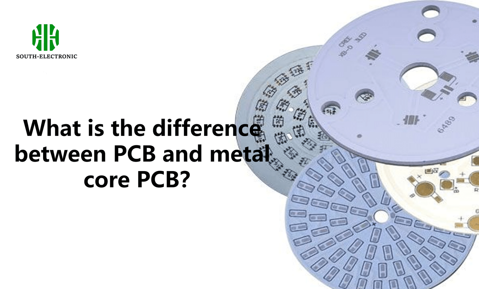
What is the difference between PCB and metal core PCB?
Printed Circuit Boards (PCBs) are the backbone of modern electronics, forming the foundation for almost every electronic device. They connect electronic components, allowing the transmission of electrical signals. However, as technology has developed, the demand for specialized PCBs has grown, which lead to the development of various types, including Metal Core PCBs (MCPCBs). Let’s explore the differences between standard PCBs and MCPCBs, focusing on their structure, materials, applications, and advantages.
What is a Standard PCB?
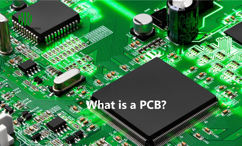
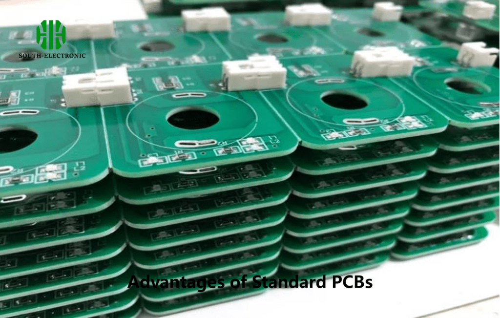
A standard PCB is a laminated sandwich structure made from conductive and insulating layers. The primary material used is fiberglass-reinforced epoxy resin, often called FR-4. The board consists of multiple layers:
- 1.Base Material: The substrate is usually made of FR-4, which provides mechanical support and insulation. It has good electrical properties and is flame-resistant.
- 2.Copper Layer: On top of the substrate, a thin layer of copper is laminated. This copper layer is etched to form conductive pathways, known as traces, which connect various components.
- 3.Solder Mask: The solder mask is a protective layer applied over the copper traces to prevent accidental short circuits and corrosion. It also gives the PCB its characteristic green color.
- 4.Silkscreen: The silkscreen layer is used to print labels, logos, and component references, aiding in assembly and troubleshooting.
What is a Metal Core PCB?
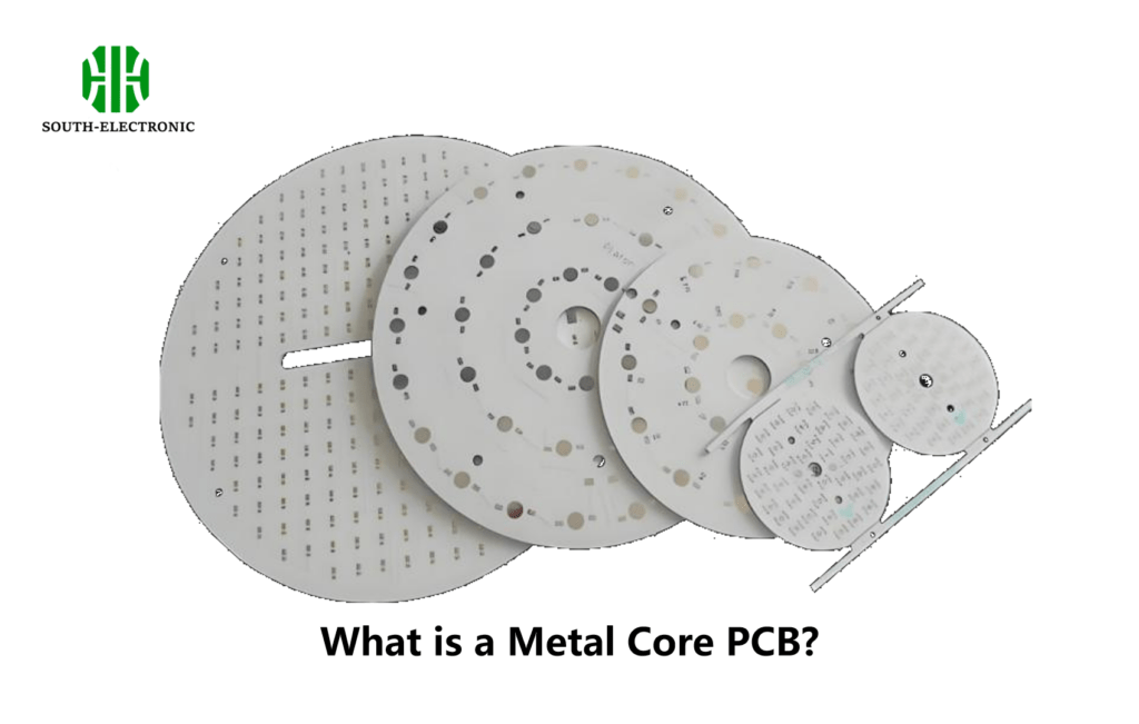
A Metal Core PCB (MCPCB), sometimes referred to as a Metal-Clad PCB, is a type of PCB that includes a metal base layer in addition to the standard layers found in regular PCBs. The metal core serves as a heat spreader, significantly improving thermal management. The key components of an MCPCB include:
- 1.Metal Core: The metal core is usually made of aluminum or copper. It provides excellent heat dissipation and mechanical stability.
- 2.Thermal Conductive Layer: A dielectric layer with high thermal conductivity is placed between the metal core and the copper layer. This layer transfers heat away from the components and into the metal core.
- 3.Copper Layer: Similar to standard PCBs, the copper layer forms the electrical circuit by connecting different components.
- 4.Solder Mask and Silkscreen: These layers function the same as in standard PCBs, providing protection and labeling.
Structural Differences
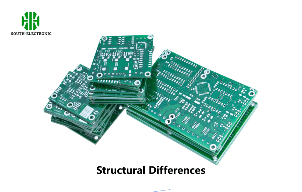
The most significant structural difference between standard PCBs and MCPCBs is the metal core in MCPCBs. While standard PCBs rely solely on the FR-4 substrate for structural integrity and insulation, MCPCBs integrate a metal layer to enhance heat dissipation.
Thermal Management: In standard PCBs, heat is dissipated through the FR-4 material, which has relatively low thermal conductivity. This can be a limitation in high-power applications where excessive heat can damage components or reduce performance. In contrast, MCPCBs efficiently transfer heat away from critical components, thanks to their metal cores, making them ideal for high-power applications.
Thickness: MCPCBs tend to be thicker than standard PCBs due to the additional metal layer. This can impact the overall design and weight of the electronic device.
Material Differences
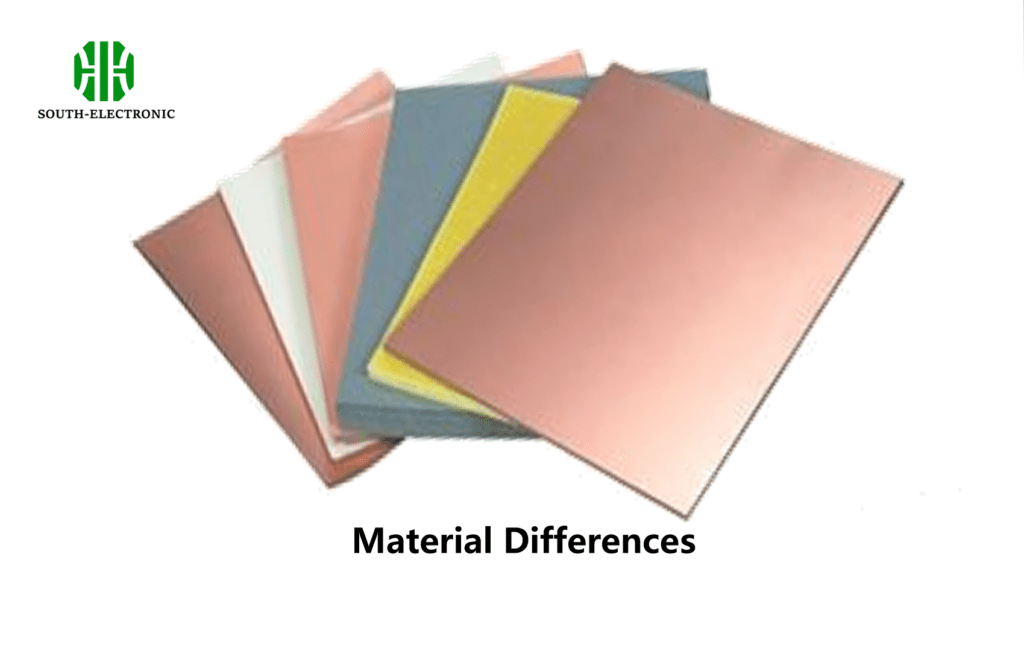
The materials used in standard PCBs and MCPCBs differ primarily in the base and dielectric layers.
FR-4 vs. Metal Core: Standard PCBs use FR-4, a glass-reinforced epoxy resin known for its excellent electrical insulation properties. MCPCBs use metal (aluminum or copper) as the base material. Aluminum is lightweight and has good thermal conductivity, while copper has even better thermal performance but is heavier and more expensive.
Dielectric Layer: In standard PCBs, the dielectric material is typically the same FR-4 used in the base. In MCPCBs, the dielectric layer is a thermally conductive material that helps to transfer heat from the copper layer to the metal core.
Application Differences
The choice between a standard PCB and an MCPCB often depends on the application, particularly the thermal requirements of the device.
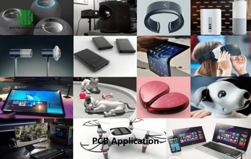
Standard PCBs: These are used in a wide range of electronic devices, from consumer electronics like smartphones and computers to industrial equipment. They are suitable for applications where heat dissipation is not a major concern.
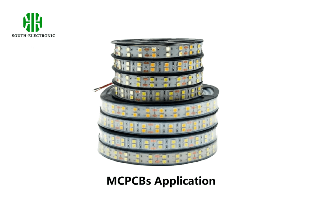
MCPCBs: These are commonly used in high-power LED lighting, power supplies, automotive electronics, and other applications where efficient heat dissipation is crucial. For example, in LED lighting, the heat generated by the LEDs needs to be quickly dissipated to prevent damage and maintain performance. MCPCBs are ideal for this purpose due to their superior thermal management capabilities.
Advantages and Disadvantages
Each type of PCB has its own set of advantages and disadvantages.
Advantages of Standard PCBs:
- 1.Cost-Effective: Standard PCBs are generally less expensive to manufacture than MCPCBs, making them suitable for mass production.
- 2.Versatile: They are highly versatile and can be used in a wide range of applications, from simple gadgets to complex systems.
- 3.Lightweight: Standard PCBs are lighter in weight, which is beneficial in portable electronic devices.
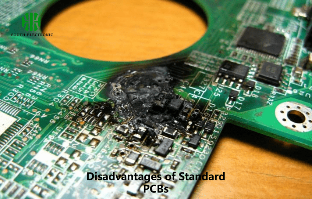
Disadvantages of Standard PCBs:
1.Poor Thermal Management: They do not dissipate heat as efficiently as MCPCBs, which can limit their use in high-power applications.
2.Limited Power Handling: Standard PCBs may struggle with high-power components, leading to overheating and potential failure.
Advantages of MCPCBs:
1.Superior Thermal Management: The metal core efficiently dissipates heat, extending the lifespan of components and improving performance.
2.Durability: MCPCBs are more robust and can withstand higher mechanical and thermal stress.
3.High-Power Applications: They are ideal for high-power applications where standard PCBs would fail due to overheating.
Disadvantages of MCPCBs:
1.Higher Cost: The addition of a metal core and thermally conductive materials makes MCPCBs more expensive to produce.
2.Heavier: MCPCBs are generally heavier due to the metal core, which can be a drawback in some applications.

Conclusion
The choice between a standard PCB and an MCPCB depends largely on the specific needs of the application. Standard PCBs are suitable for a wide range of electronics where thermal management is not a primary concern.
In contrast, MCPCBs offer significant advantages in high-power applications where heat dissipation is critical. Understanding these differences helps engineers and designers select the right type of PCB for their projects, ensuring optimal performance and longevity of the electronic device.
As technology continues to evolve, the demand for specialized PCBs like MCPCBs is likely to grow, driven by the need for more efficient and reliable electronic applications.

