Your circuit keeps crashing randomly? Voltage spikes ruin sensitive components without warning. Save your project from chaos with this hidden defender.
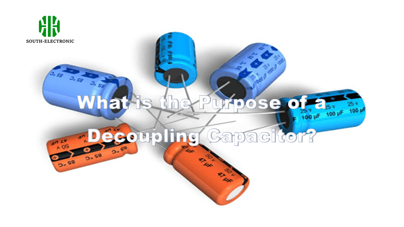
A decoupling capacitor stabilizes power for integrated circuits. It reduces noise from voltage fluctuations. Place it near an IC’s power pin. It acts as a miniature battery. This provides instantaneous current during switching. The result is cleaner power delivery.

I lost three prototypes to power noise before understanding this fix. Now let’s explore how decoupling saves digital systems.
Why Do Digital Circuits Scream for Decoupling Capacitors?
Chips suddenly demand huge current when switching states? Power lines sag under brief starvation. Stop logic errors crippling your device.
Digital circuits need decoupling capacitors due to fast switching speeds. Transistors turn on/off rapidly. This creates sharp current spikes. Power supplies respond too slowly. Without local energy reserve, voltage drops trigger errors. Capacitors fill these nanosecond gaps.
Critical Roles in Current Spikes
Logic gates switch states incredibly fast. Each transition requires tiny bursts of current. Thousands flip simultaneously during clock pulses. This creates cumulative power spikes.

Noise Amplification Risks
Voltage dips trigger oscillations in circuits. Ground bounce propagates across shared rails. Radiated RF noise can disrupt nearby components. Multiple ICs create additive interference.
| Problem | Impact | Solution Role |
|---|---|---|
| Sudden current demand | Voltage droop at IC power pin | Provides localized energy release |
| Inductive response lag | Voltage overshoot after transitions | Absorbing excess energy |
| Shared rail fluctuations | Signal crosstalk between ICs | Isolates noise between components |
Decoupling vs. Bypass Capacitor: Is There Any Difference?
Confused which name to use? Design guides suggest both terms equally. But subtle distinctions exist in functionality.
Decoupling and bypass capacitors share identical physical components. Both filter power supply noise. But the primary focus is different. Decoupling targets voltage stabilization. Bypassing shunts high-frequency noise to ground. The distinction lies in noise source management.

Voltage Stabilization Role
Decoupling capacitors act as micro-scale batteries. They supply immediate power during demand spikes. This prevents voltage sags at logic components. Energy storage maintains steady DC levels.
Frequency Filtering Mechanism
Bypass capacitors short high-frequency transients. They redirect noise away from sensitive paths. Radio-frequency interference requires low-impedance paths. Capacitors serve as frequency-dependent shorts.
Shared Physical Implementation
The same ceramic capacitor serves both roles in practice. Placement and connections define its operation. "Decoupled capacitor" implies placement near IC power pins. Low ESL capacitors perform better at high frequencies.
| Function | Decoupling Capacitor | Bypass Capacitor |
|---|---|---|
| Primary goal | Maintain voltage stability | Divert noise to ground |
| Target frequencies | Medium switching noise | High-frequency spikes |
| Circuit impact | Energy buffer reservoir | Shunt pathway for noise |
How to Choose the 0.1μF "Magic Number"? The Science Behind Size
Tempted to copy reference designs? Default values often fail performance demands. Select capacitor values using physics.
Choose decoupling caps based on impedance needs. Higher frequencies require smaller capacitors. The 0.1μF value works near 15MHz. Calculate using: ΔV = (I × Δt) / C. High-speed devices need multiple values. Parallel combinations beat single units.

Resonant Frequency Priority
All capacitors have parasitic inductance. This sets resonant frequency peak impedance. Below resonance, caps act capacitive. Above, inductance dominates behaviour. 0.1μF ceramic resonates around 15MHz with 1nH ESL. This covers common logic speeds.
Current Demand Calculations
Compute minimum capacitance using energy deficit. Measure the largest current spike (I). Determine maximum time gap (Δt). Select ΔV tolerance. Then C = I × Δt / ΔV. Modern ICs often require multiple 100nF caps.
Practical Value Selection
Mix 0.01μF and 10μF capacitors in parallel. Cover wide frequency spectrum. Smaller packages lower inductance. X7R ceramics provide stability. Keep leads extremely short.
| Frequency Range | Ideal Capacitor Value | Effect |
|---|---|---|
| >100 MHz | 0.01μF or smaller | Address fastest transients |
| 10-100 MHz | 0.1μF standard | Default for medium-speed logic |
| 2cm from IC pin | Slow response to spikes | Position within 5mm of IC |
| Shared power traces | Noise transfer between ICs | Dedicated short capacitor traces |
| Vias between connection | Inductive resistance increases | Direct surface mount pads |
| Bad ground connections | Restricted current return paths | Connect to solid ground plane |
Can Multiple Capacitors Beat One "Super Capacitor"?
Tried solving noise with one large capacitor? Resonances create impedance hills. Multiple capacitors flatten overall impedance curve.
Using multiple values works better than single capacitors. Different capacitance values cover different frequencies. Parallel combination achieves lower overall impedance. Avoid resonant impedance peaks at noise frequencies. Place grouped capacitors near each IC.

Frequency Coverage Principle
Individual capacitor has resonance points. Impedance becomes high beyond this frequency. But digital noise contains harmonics. Multiple capacitor values cover broad spectrum. The 0.1uF and 0.01uF combination handles wider bandwidth.
Parasitic Inductance Stacking
Sharing vias introduces common inductance. This cancels parallel benefits. Multiple capacitors require separate connections. Use low-inductance configurations. Star point connections perform poorly.
Implementation Guidelines
Combine 0.1μF, 0.01μF, and 1μF ceramics. Place smaller values closer to pins. Avoid daisy chaining connection paths. All capacitors need direct access to planes. Space them evenly around high-pin-count devices.
| Value Combination | Frequency Coverage | Benefit |
|---|---|---|
| Single 1μF | Best at 1-10 MHz | Wide coverage gaps |
| 0.1μF + 0.01μF + 1μF | 100 kHz – 100 MHz | Seamless impedance control |
| Six 0.1μF capacitors | 5-25 MHz dominant | Lower equivalent series inductance (ESL) |
Do Decoupling Caps Overheat?
Capacitors bulge during heavy operations? Temperature rises indicate approaching failure. Prevent premature decoupling capacitor death.
Decoupling capacitors can overheat from ripple currents. Excessive temperature degrades electrolytic types. ESR increases generate more heat. Ceramics crack under thermal stress. Voltage bias affects operating temperature.

Ripple Current Heating
Switching currents flow through the capacitor. Current equals voltage swing divided by impedance. High ESR creates significant power loss: P = I² × ESR. Even milliohm ESR causes heating.
Environmental Contributors
External heating combines with internal loss. Nearby components heat nearby capacitors. Poor board airflow restricts cooling. Enosures amplify temperature effects. Ambient temperature affects component ratings. Derate parameters at elevated temperatures.
Failure Prevention
Select capacitors rated for ripple currents. X5R/X7R ceramics handle moderate stress. Polymer capacitors outperform in high-current situations. Distribute current across multiple caps. Thermal vias under components help cooling.
| Stress Factor | Effect | Mitigation Strategy |
|---|---|---|
| High ripple current | Core heating, reduced lifetime | Use multiple capacitors in parallel |
| External heat sources | Degraded dielectric performance | Increase clearance from hot components |
| Operation near ratings | Accelerated aging | Select higher temp rating components |
| Voltage de-rating | Reduced capacitance under bias | Choose proper voltage-rated capacitors |
Conclusion
Decoupling capacitors combat power noise through smart placement and values. Proper implementation prevents system failures. Use multiple capacitors strategically for best stability.


