

You need reliable electronics. Weak connections fail when stressed. Through-hole builds strength from the inside.
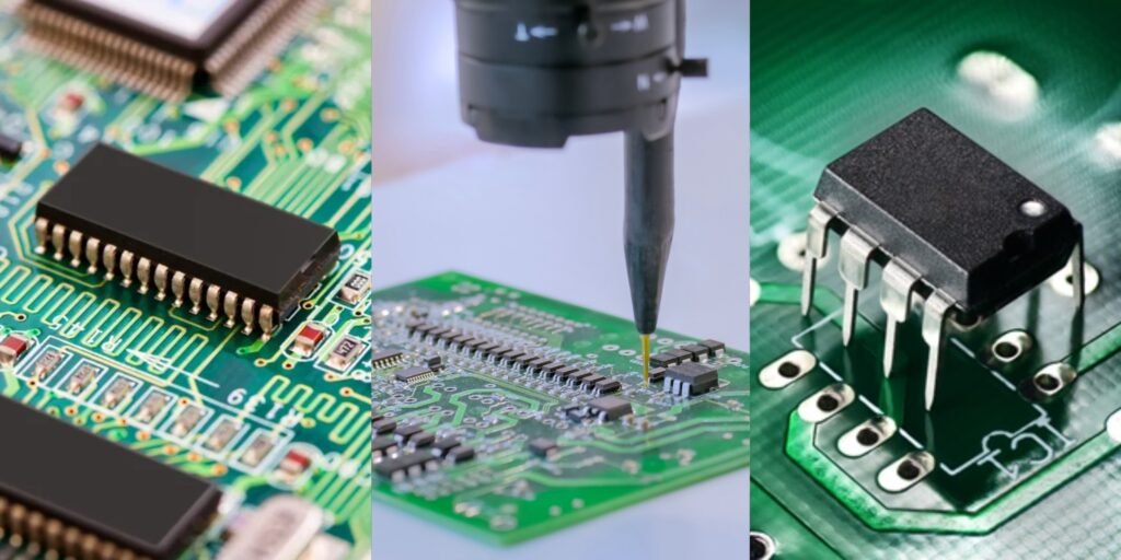
Through-hole technology[^1] mounts components by inserting leads through PCB holes, soldering them securely on the opposite side. This creates robust physical and electrical bonds ideal for high-stress applications[^2].
Now understand when and how to use this reliable method effectively across your projects.
When to choose through hole vs. surface mount?
Prototyping often brings frustration. Components detach during testing. Select the right method to prevent failures.
Through-hole suits prototypes, heavy components[^3], and high-vibration environments. Surface mount excels in compact designs and automated production for cost efficiency.
Application Requirements Determine Choice
Consider these factors during selection:
| Factor | Through-Hole Best For | Surface Mount Best For |
|---|---|---|
| Physical Stress | High vibration/impact devices | Stationary devices |
| Component Size | Large transformers, connectors | Tiny capacitors, chips |
| Testing | Manual adjustments | Permanent installations |
| Board Space | Simple layouts | Complex circuitry |
Through-hole offers accessibility for quick modifications during development. The leads extending through boards simplify manual circuit testing significantly. Surface mount allows tighter component placement but often requires special tools. Projects facing mechanical pressure always gain extra durability from through-hole connections. Weight matters too – heavy parts anchor better with through-hole mounting. Choose based on what your specific build demands most. This prevents redesigns later.
How is through hole PCB assembly done?
Inaccurate assembly wastes components. I’ve seen boards ruined before testing. Follow proven steps for success.
Assembly involves component insertion and soldering. First place parts in correct holes. Then solder connections manually or with wave soldering equipment.

Six-Step Assembly Procedure
Executing these stages ensures reliability:
| Stage | Key Action | Importance |
|---|---|---|
| Placement | Insert leads through matching holes | Physical anchoring |
| Board Support | Secure board horizontally | Prevents misalignment |
| Soldering | Apply iron to junction pad/lead | Forms electrical bond |
| Solder Flow | Feed wire to create concave fillet | Ensures full connectivity |
| Inspection | Verify shiny, smooth joints | Detects flaws early |
| Trimming | Cut excess leads flush | Eliminates short risks |
Component orientation matters most during placement. Match part markings to board indicators. Secure heavier pieces first so smaller ones don’t shift unexpectedly. Soldering temperature should melt solder within two seconds – excessive heat damages boards and components alike. Consistent fillet shapes indicate proper fusion. Always test connections physically after assembly completes before applying power to avoid accidental damage. This maintains quality throughout production.
What are the techniques, tips, and troubleshooting for soldering through hole components?
Cold solder joints cause mysterious failures later. I once spent hours finding one bad connection. Master these methods to avoid headache.
Apply iron tip to both lead and pad simultaneously. Feed solder opposite the iron. Remove iron after solder flows fully around the lead.

Problem-Solving Guide
Address frequent issues with these approaches:
| Issue | Cause | Fix |
|---|---|---|
| Blobby Joint | Insufficient heat | Reheat with iron contact |
| Partial Wetting | Dirty surfaces | Clean with flux |
| Solder Bridges | Excess solder | Use desoldering wick |
| Component Shifting | Premature movement | Hold part during cooling |
| Burn Marks | Heat too high | Reduce iron temperature |
| Joint Cracks | Movement during cooling | Secure board properly |
Tip: Touch solder to the junction – never directly to the iron. Keep iron tips clean using damp sponges to ensure maximum heat transfer efficiency. For multi-pin components, solder diagonal corners first for stable alignment throughout the process. When soldering heat-sensitive parts, employ heat sinks clipped onto leads between component and board to prevent thermal damage effectively. Practice makes soldering quality consistent over time.
Conclusion
Through-hole provides unmatched mechanical strength. Master component selection, assembly methods, and soldering skills for dependable builds every time.
[^1]: Explore this link to understand the fundamentals of through-hole technology and its advantages in electronics.
[^2]: Learn about high-stress applications to see how through-hole technology can enhance reliability in demanding environments.
[^3]: Find resources on managing heavy components in PCB design to ensure stability and performance.

