
Struggling to fit bulky PCBs in small devices? It slows miniaturization—FPCs solve this.
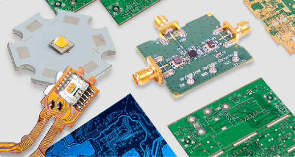
FPCs are flexible printed circuits with PI/PET bases. They bend, reduce device size, suit moving parts, and differ from rigid PCBs, aiding modern device design.
Below, I break down FPC’s key differences from PCBs, materials, uses, and how to pick the right maker for your project.
How Do FPC Flexible Circuits Differ from Traditional PCB Rigid Boards?
Confused between FPC and PCB for your device? Picking wrong hurts design—here’s the clear difference.
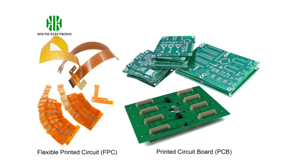
FPC uses flexible PI/PET materials, bends easily, and suits small/moving parts. PCB uses rigid FR4, can’t bend, and works for stable parts like motherboards.
Core Differences Between FPC and PCB
In my years of designing electronics, I’ve seen projects fail because teams mixed up FPC and PCB. The table below breaks down their key differences to avoid that mistake:
| Feature | FPC Flexible Circuit | PCB Rigid Board |
|---|---|---|
| Base Material | Polyimide (PI) or Polyester (PET) | FR4 (fiberglass-reinforced epoxy) |
| Flexibility | Can bend, fold, and withstand 1M+ dynamic bends | Cannot bend; rigid structure |
| Key Use Cases | Foldable screens, camera modules, battery connectors | Computer motherboards, phone main boards, stable sensors |
| Space Efficiency | Fits 3D layouts; reduces device size by 40%+ | Limited to 2D layouts; needs more space |
| Durability in Motion | Handles repeated movement without wire damage | Fails if bent; cracks under movement |
I once worked on a foldable phone prototype with a PCB—it cracked after 500 bends. Switching to FPC let it pass 1 million bends, which is the industry standard for foldables.
What’s the Difference Between FPC Flexible Circuits and Rigid-Flex Boards?
Wondering if FPC or rigid-flex fits your design? The wrong choice adds cost—let’s clarify.
FPC is fully flexible (all PI/PET). Rigid-flex has both flexible (PI) and rigid (FR4) parts. Rigid-flex costs more but suits mixed rigidity needs.
Key Contrasts Between FPC and Rigid-Flex Boards
Rigid-flex boards are a hybrid, and I’ve used them for projects that need both a stable mount (like a sensor) and a bending part (like a connector). Here’s how they stack up to FPCs:
| Feature | FPC Flexible Circuit | Rigid-Flex Board |
|---|---|---|
| Flexibility Range | Fully flexible; bends in all directions | Partial flexibility (only PI sections bend) |
| Production Cost | Lower (simpler process, fewer materials) | Higher (2x–3x FPC cost; needs rigid-flex bonding) |
| Production Complexity | Fewer steps (40+ vs. 60+ for rigid-flex) | More complex (requires aligning rigid/flex layers) |
| Ideal Applications | Fully moving parts (e.g., watch bands, foldable hinges) | Devices needing both stability and flexibility (e.g., medical devices with a rigid display and flexible probe) |
| Part Count Reduction | Cuts wire harnesses but needs extra fasteners | Cuts 30%+ part count (combines rigid and flex into one) |
Last year, I used a rigid-flex board for a wearable health monitor. It had a rigid section for the battery (needs stability) and a flexible section that wraps around the wrist. This design eliminated 4 connectors and 2 separate PCBs, making the device 25% lighter.
What Materials Make Up FPC Flexible Circuits?
Unsure what materials make FPCs work? Bad material choices ruin reliability—here’s the breakdown.
FPCs use 3 core materials: FCCL, coverlay (circuit protection), and bond film (layer adhesion). PI is the most reliable base material.
Core Materials in FPCs and Their Roles
The right materials are critical—I’ve had FPCs fail because a supplier used PET instead of PI for a high-heat project. Below is what each material does and why it matters:
| Material | Primary Role | Key Properties |
|---|---|---|
| FCCL | FPC’s base; carries electrical signals | PI-based FCCL: high temperature resistance, 1M+ bend cycles. PET-based FCCL: cheaper but weak at >120°C |
| Coverlay | Protects copper circuits from damage/dust | Made of PI/PET + adhesive; comes in yellow/white/black (black for EMI shielding) |
| Bond Film | Bonds FPC layers together; insulates layers | Can be with/without a base; 0.01mm–0.1mm thick; resistant to moisture |
I always recommend PI-based FCCL for projects involving heat (like car electronics or LED modules). PET-based FCCL is only good for low-heat, low-stress uses (like simple toy circuits). The coverlay color also matters—black coverlay is my go-to for devices sensitive to electromagnetic interference (EMI), like GPS modules.
How Do FPC Substrates, Coverlays, and PI Stiffeners Differ?
Mixing up FPC substrate, coverlay, or stiffener? It causes design flaws—let’s sort them out.
Substrates are FPC’s base (PI+copper), coverlays insulate circuits, and stiffeners add rigidity. Each has unique thickness, color, and purpose.

Detailed Differences Between the Three Components
I’ve seen designers use a stiffener where a coverlay is needed—this adds unnecessary thickness and cost. The table below clears up their roles:
| Feature | FPC Substrate | FPC Coverlay | PI Stiffener |
|---|---|---|---|
| Primary Function | Base layer; holds copper traces for signals | Insulates copper traces; prevents short circuits | Adds rigidity to specific areas (e.g., connectors) |
| Thickness Range | 0.025mm (1mil) to 0.125mm (5mil) | 0.012mm (0.5mil) to 0.025mm (1mil) | 0.075mm to 0.25mm (customizable) |
| Color Options | No choices (natural PI color: amber) | Yellow, white, black (most common: yellow) | Darkens with thickness (0.075mm: brown; 0.25mm: black) |
| Key Use Example | Entire FPC base (e.g., phone camera FPC) | Covers copper traces on a battery connector FPC | Added to gold finger areas for easier插拔 |
When designing FPCs with ZIF (zero insertion force) connectors, I always add a 0.1mm PI stiffener. Without it, the FPC bends when inserting the connector—this damages the traces over time. Stiffeners also make thin FPCs easier to handle during assembly; I’ve cut assembly time by 15% just by adding small stiffeners to hard-to-grab areas.
What Are the Application Advantages and Development Prospects of FPC?
Want to know why FPCs are booming? Missing their benefits means falling behind—here’s why they matter.
FPCs are thin, light, and flexible. They’re key for 5G phones, wearables, and car electronics, and demand will grow as devices get smaller.

Top Advantages and Growth Areas for FPCs
FPCs have changed how I design electronics—they let me create devices that were impossible with PCBs. Below are their biggest advantages and where they’re growing fastest:
Key Application Advantages
- High Density: FPCs have smaller line widths (0.1mm vs. 0.2mm for PCBs), so I can fit more traces in the same space. This is critical for 5G phones, which need more signal paths.
- Weight Savings: FPCs are 70% lighter than PCBs. For wearables like smartwatches, this cuts device weight by 20%–30%—a big win for user comfort.
- Durability: PI-based FPCs handle 1 million+ bends. I tested an FPC in a smart band—it lasted 2 years of daily wrist movement without failing.
Fast-Growing Application Areas
| Industry | Key FPC Uses | Growth Driver |
|---|---|---|
| Smartphone | Camera modules, foldable screens, battery connectors | 5G and foldable phones (10–15 FPCs per phone) |
| Wearables | Smartwatch bands, fitness tracker sensors | Demand for lightweight, flexible devices |
| Car Electronics | EV sensors, infotainment displays, wiring harnesses | EV growth (cars need 50% more FPCs than gas vehicles) |
I expect FPC demand to grow 15%–20% per year over the next 5 years. Car electronics will be the biggest driver—EVs need FPCs for their complex sensor networks and flexible wiring. I’m already working on an EV project that uses 25 FPCs (vs. 10 for a gas car) to connect cameras, batteries, and touchscreens.
What Should You Consider When Choosing an FPC Manufacturer?
Picking a bad FPC maker delays projects—want to avoid that? Here’s what to check first.
Check if the maker meets your specs (tolerances, materials), produces your batch size, and matches your budget/delivery time. Ask about their quality tests.
Critical Factors for Choosing an FPC Maker
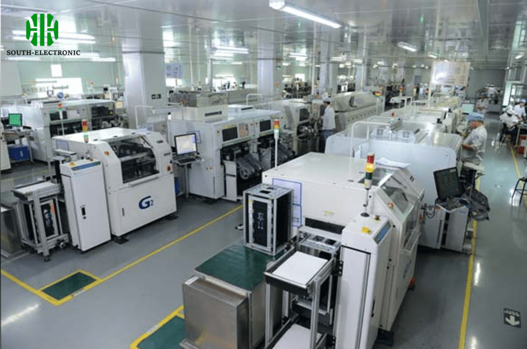
I’ve worked with 10+ FPC makers, and the wrong one can delay your project by weeks. Below is what to ask and why it matters:
| Consideration | What to Ask the Manufacturer | Why It Matters |
|---|---|---|
| Spec Compatibility | "Can you make FPCs with 0.1mm line widths and PI substrate?" | If they can’t meet your specs, the FPC won’t work in your device. |
| Batch Size Capability | "Do you handle small batches (10–50) or only large orders (1000+)?" | Small-batch makers are better for prototypes; large-batch for mass production. |
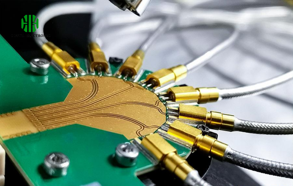
| Quality Testing | "Do you test FPCs for bend durability and signal integrity?" | Untested FPCs have 20%+ failure rates—testing cuts this to 2% or less. |
| Delivery Time | "How long does a 100-piece order take?" | Late FPCs delay your entire production line. |
| Material Stock | "Do you keep PI substrate and black coverlay in stock?" | Stock shortages can add 2–4 weeks to lead time. |
Last year, I chose a maker who said they could handle 0.08mm line widths—but their first batch had 30% of traces shorted. It turned out they didn’t have the right laser equipment. Now, I always ask for a sample before placing a large order—it saves time and money.
What Is an FPC Stiffener, and What Is Its Purpose?
Confused why FPCs need stiffeners? Without them, connectors fail—here’s their key role.
FPC stiffeners are rigid parts (PI/metal) added to specific areas. They support connectors, SMT parts, and make FPCs easier to handle.
Top 5 Purposes of FPC Stiffeners
Stiffeners are often overlooked, but they’re critical for reliability. In my projects, stiffeners have cut FPC failure rates by 40%. Below are their main uses:
| Purpose | Example Use Case | Benefit to Your Project |
|---|---|---|
| Support Connectors | Adding a stiffener to a ZIF connector area | Prevents FPC bending during insertion; extends connector life. |
| Stabilize SMT Parts | Stiffener under a chip resistor on a thin FPC | Keeps parts flat during soldering; avoids cold joints. |
| Improve Handling | Small stiffeners on narrow FPC edges | Makes FPCs easier to grab during assembly; cuts assembly errors. |
| Maintain Flatness | Stiffener under a touch sensor FPC | Ensures the sensor stays flat; improves accuracy. |
| Protect Bend Areas | Stiffener near a rigid-flex junction | Increases bend radius; prevents trace cracking. |
I once had an FPC fail because it didn’t have a stiffener under a micro USB connector. Every time the user plugged in the cable, the FPC bent—after 50 uses, the traces broke. Adding a 0.15mm PI stiffener fixed the issue, and the FPC lasted through 1000+ plug-ins.
What Factors Affect the Processing Cost of FPC Flexible Circuits?
Surprised by FPC cost quotes? Not knowing cost drivers leads to overspending—here’s what impacts price.
FPC cost depends on materials (PI vs. PET), precision (line width), batch size, and process steps (plating, drilling). Higher quality means higher cost.

Key Factors That Raise or Lower FPC Costs
I’ve helped clients cut FPC costs by 20% by adjusting these factors. Below is what to focus on:
| Cost Factor | How It Impacts Price | Example Savings Tip |
|---|---|---|
| Base Material | PI costs 2x more than PET; no-adhesive PI costs 3x more than adhesive PI | Use PET for low-heat, low-stress projects (e.g., toys) instead of PI. |
| Line Width/Precision | Line widths <0.1mm add 15%–20% to cost | Use 0.15mm line widths if your design allows—no loss in performance for most uses. |
| Batch Size | 10-piece orders cost 5x more per unit than 1000-piece orders | Combine small orders into one batch if possible. |
| Process Steps | Plating (e.g., gold) adds 30% cost; extra drilling adds 10% | Use tin plating instead of gold for non-connector areas; reduce unnecessary holes. |
| Quality Requirements | Military-grade FPCs cost 4x more than consumer-grade | Only use military specs if your device needs it (e.g., aerospace)—consumer specs work for most electronics. |
Last month, a client wanted gold plating on their entire FPC. I suggested gold only on the connector area (where it’s needed) and tin elsewhere. This cut their cost by 25% without hurting performance. Small adjustments like this make a big difference in FPC budgets.
Conclusion
FPCs are essential for modern small, flexible devices. Understanding their differences from PCBs/rigid-flex, materials, and cost drivers helps you design and source better.

