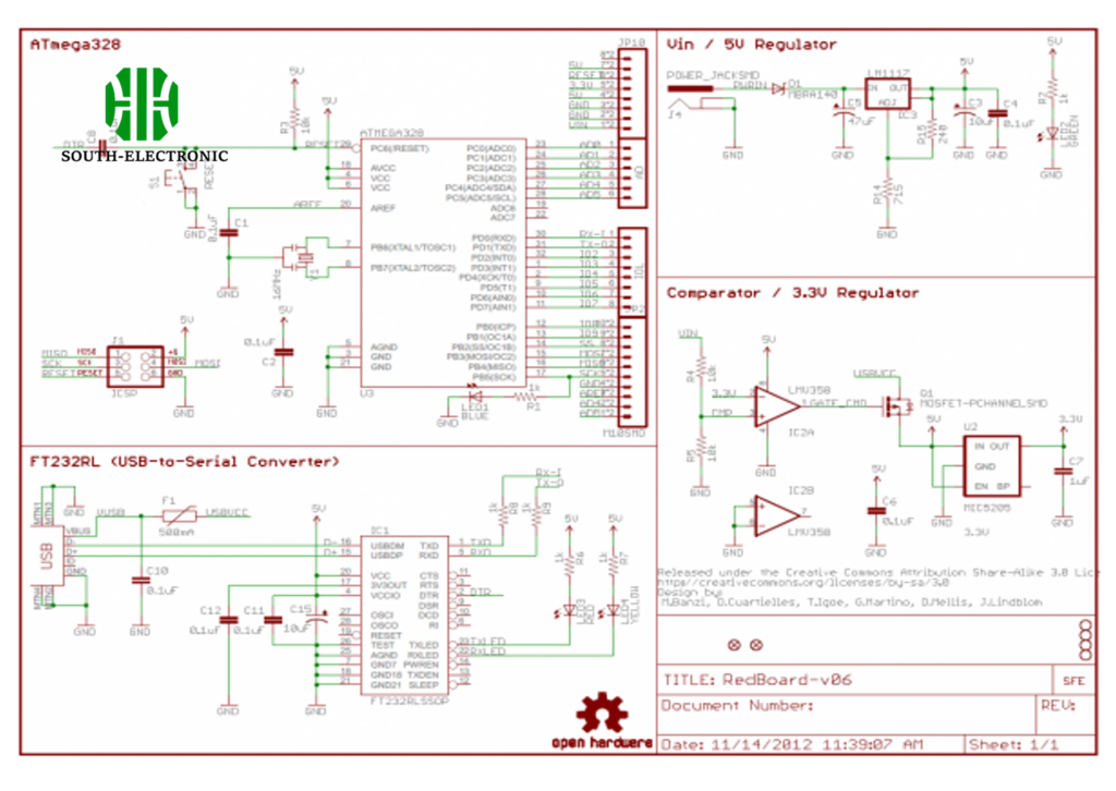
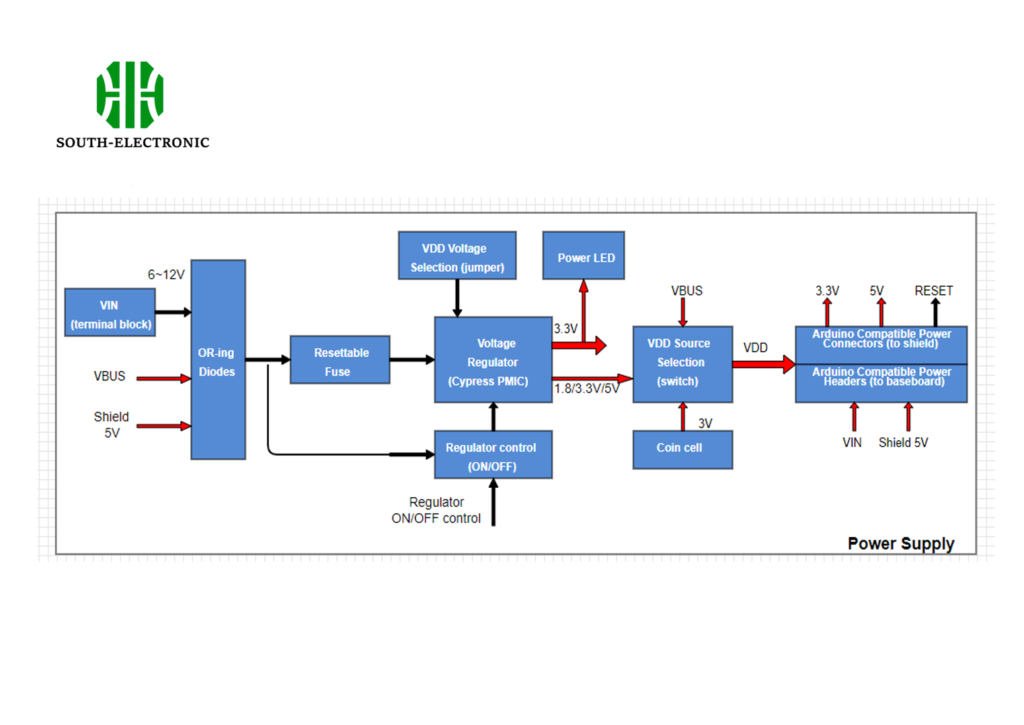
What's the Meaning of Schematic Diagram?
You need a schematic diagram to see an electrical circuit, process, or system in a clear and simple way. It shows you all the parts and how they work together, without worrying about where they are. Think of a schematic diagram as a subway map. The subway map uses simple lines and color-coded symbols to represent the routes and stations. A schematic diagram uses standardized symbols to represent the components of a system. It doesn't show the physical layout of the components, but rather how they connect and interact. It makes complex information more digestible and easier to understand.

The Importance and Applications of Schematic Diagrams
Schematic diagrams are widely used in various fields, including electronics, engineering, chemistry, and biology. They help in:
- Design and Development: Assisting in the design of new circuits and systems.
- Troubleshooting: Identifying issues in an existing system.
- Documentation: Providing a standardized way to document the design and function of systems.
Common Applications of Schematic Diagrams
| Field | Application Example |
|---|---|
| Electronics | Circuit design and troubleshooting |
| Engineering | System modeling and simulation |
| Chemistry | Chemical reaction pathways |
| Biology | Biochemical pathways and processes |

How to Read a Schematic
To read a schematic diagram, you need to be familiar with the symbols and conventions used to represent different components and their connections. Here’s a step-by-step guide to help you get through a schematic:
- Identify Symbols: Start by identifying the symbols used in the diagram. Each symbol represents a different component, such as resistors, capacitors, transistors, and more. Familiarize yourself with these symbols; you might find it helpful to have a reference guide handy initially.
- Understand Connections: Lines on a schematic represent the connections between components. A solid line indicates a direct connection, while a line that jumps over another with a 'bridge' indicates that the wires do not connect.
- Follow Nets: "Nets" are groups of electrically connected points. Look for labels, which are often alphanumeric, next to the symbols or along connection lines. These labels help you understand where the connection travels throughout the schematic.
- Check for Power and Ground: Identify the power sources and grounds. These are critical for understanding how power flows through the circuit. Power is usually indicated by an upward-facing arrow or a plus sign, while ground symbols might be shown as a set of horizontal lines or a downward arrow.
- Look for Input and Output: Determine the inputs and outputs of the circuit. This helps in understanding the purpose of the circuit. Inputs could be signals from other components, and outputs might be connections to other parts of a larger system.
- Note Component Values: Pay attention to any values next to the components, such as resistance in ohms or capacitance in farads. These values are crucial for understanding the behavior of the circuit.
- Sequential Analysis: Begin at the power source, and trace how the current flows from one component to the next. This method helps you understand the circuit's operation step-by-step.
- Use Annotations: Many schematics include annotations that provide additional information about voltage levels, settings, or operational notes. These can be invaluable for deeper understanding.
If you follow these steps, you'll be better able to understand and interpret schematic diagrams, whether you're troubleshooting existing circuits or designing new ones.

Understanding Schematic Symbols
Schematic symbols are pictures that represent components. These pictures tell you what the components do and what they look like. For example, a resistor is usually shown as a squiggly line, and a capacitor might be shown as two parallel lines.
Common Symbols and Their Meanings
- Resistor (R): Limits current flow, represented by a zigzag line.
- Capacitor (C): Stores energy in an electric field, shown as two parallel lines.
- Diode (D): Allows current to flow in one direction, depicted as a triangle pointing to a line.
- Transistor (Q): Used to amplify or switch electronic signals, with different symbols for NPN and PNP types.

How to Create a Schematic Diagram
Creating a schematic diagram involves several key steps:
- Symbol Generation:Symbols represent the components in the diagram. These are often predefined in CAD software but can also be custom-created.
- Component Placement:Place the symbols logically, maintaining an easy-to-follow flow.
- Pin Numbering and Naming:Ensure each pin is numbered and named accurately to correspond with the physical components.
- Adding Connections:Draw lines (nets) to represent the electrical connections between components.
- Documentation and Labels:Include important information like component values, operating conditions, and other specifications.

To ensure clarity and functionality in schematic diagrams, follow these best practices:
- Use Standardized Symbols: Stick to universally recognized symbols for components.
- Maintain Consistent Flow: Typically, signal inputs are on the left, and outputs are on the right.
- Label Nets Clearly: Use descriptive names for nets to indicate their function.
- Avoid Overcrowding: Space out components and connections to prevent confusion.
References and Further Reading
- Books: "The Art of Electronics" by Paul Horowitz and Winfield Hill
- Online Courses: Coursera's "Introduction to Electronics"
- Software Tutorials: Altium Designer and KiCad tutorials for PCB design
Schematic diagrams are indispensable tools in various technical fields, offering a simplified yet comprehensive view of systems and circuits. By mastering the use of these diagrams, professionals can enhance their design, troubleshooting, and documentation processes.


