
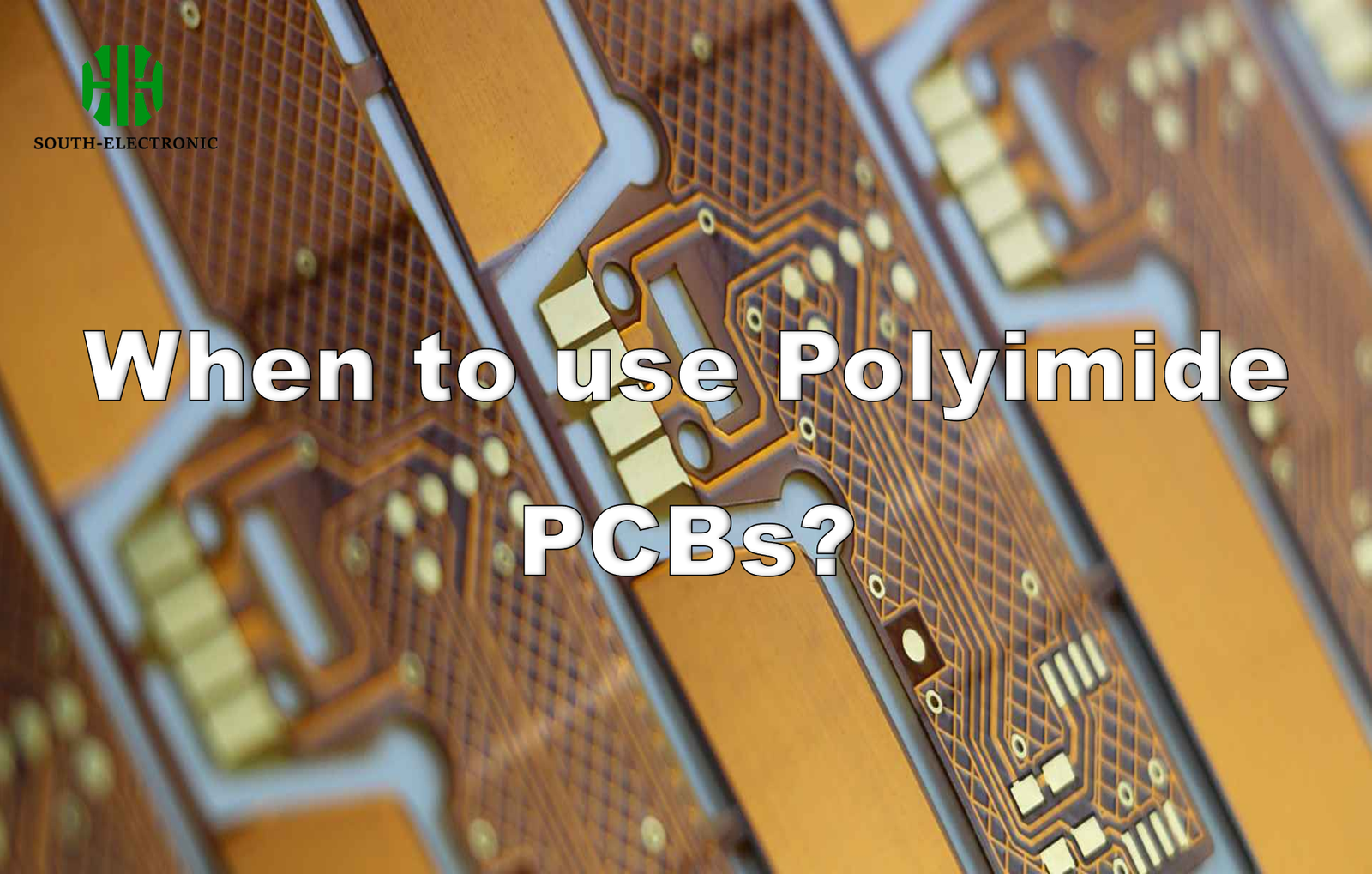
Does your device endure extreme heat, constant flexing, or harsh environments? Are FR4 or Teflon PCBs failing under pressure? Polyimide PCBs solve these frustrating reliability challenges in demanding applications.
Choose polyimide PCBs when you need exceptional flexibility, high-temperature resistance (up to 400°C), and durability. Ideal for aerospace systems, medical devices, automotive sensors, and wearables where thinner boards withstand vibration, bending, and thermal shocks better than traditional materials.

Understanding polyimide’s unique advantages and limitations helps engineers make smarter decisions. Let’s explore key questions about these specialty boards to optimize your next project.
What are the main types of Polyimide PCBs?
Seeing confusing choices? Selecting the right polyimide type prevents costly redesigns and performance gaps.
Three primary types exist: flexible polyimide PCBs for bendable circuits (like foldable phones), rigid polyimide PCBs for high-heat environments (engine controls), and rigid-flex hybrids combining both advantages (used in satellites). Manufacturers tailor each to specific thermal and mechanical needs.
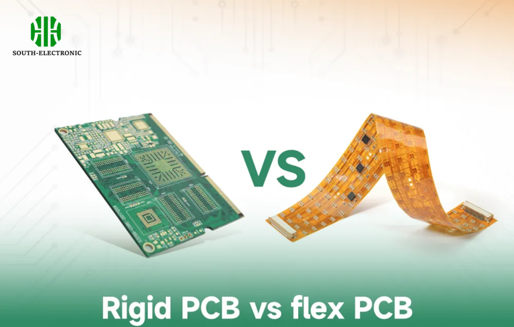
Matching PCB types to application demands
Three factors determine your best option: temperature range, physical stresses, and space constraints. Flexible polyimide PCBs excel in wearable tech where constant movement occurs, while rigid polyimide PCBs serve under-hood automotive applications needing combustion chamber proximity. Rigid-flex versions (using adhesiveless polyimide cores) support complex aerospace assemblies.
Critical material properties like CTE (Coefficient of Thermal Expansion) and Tg (Glass Transition Temperature) drive selection. Study polyimide PCB material data sheets closely:
| Property | Flexible PCBs | Rigid PCBs | Key Impact |
|---|---|---|---|
| Max Bend Cycles | 100,000+ | <100 | Dynamic vs static use |
| Continuous Heat | 260°C | 340°C | Engine bay vs cabin |
| Layer Capacity | 1-8 layers | 8-30 layers | Signal complexity |
| Thickness Range | 0.05-0.3mm | 0.4-3.2mm | Device miniaturization |
Avoid failures by consulting polyimide PCB manufacturers early. Military-grade rigid polyimide PCBs add copper weights for thermal management, while medical implants use ultra-thin polyimide flex PCB stacks. Cost tradeoffs exist – thicker boards handle power but reduce flexibility. Compare polyimide vs FR4 when weight savings justify premium costs.
What tests ensure Polyimide PCB reliability?
Worried about field failures? Unverified boards risk recalls. Polyimide needs specific validations beyond standard FR4 testing.
Essential tests include thermal cycling (-55°C to 260°C), bend/fold endurance checks (100k+ cycles), and CAF (Conductive Anodic Filament) resistance exams. These confirm board stability in extreme conditions through accelerated lifespan simulations.
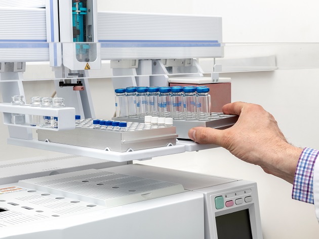
Validating performance beyond specifications
Testing must match operating environments. Automotive applications require harsh thermal shock tests mimicking cold starts and desert operation. Medical implant verification involves saline immersion and dynamic flex tests simulating body movements. Each test correlates to real-world performance metrics:
Thermal Stress Verification
- 500+ cycles from -65°C to 300°C
- Monitored for delamination and via cracks
- Exceeds basic IPC thermal standards
Mechanical Robustness Protocols
- 0.5mm radius bend testing at high frequencies
- Torsional stress simulations for aerospace gear
- Peel strength measurements post-reflow
Material Stability Exams
- Outgassing analysis for vacuum operations
- Chemical resistance against fuels/solvents
- Humidity exposure (85°C/85% RH, 1000+ hours)
Test reports from polyimide PCB manufacturers should include these plus flammability (UL94 V-0) and ionic contamination data. For flex-rigid boards, verify flex-to-hardboard transitions survive drop tests. Match test conditions to your operating envelope – aerospace requires radiation tolerance absent in consumer goods. Include these requirements early in supplier negotiations.
Why are Polyimide PCBs more expensive? How to reduce costs?
Facing budget pressure? Premium material costs concern design engineers but smart optimizations enable savings.
Higher costs stem from specialized polyimide substrates and complex processing. Save via strategic layer counts, panel utilization improvements, and avoiding unnecessary properties. Volume discounts from polyimide PCB manufacturers can cut costs 15-30%.
Balancing performance and budget
Polyimide’s expense comes from its chemistry and processing. Teflon PCBs cost more but polyimide provides better mechanical stability. Compare cost drivers and solutions:
| Cost Factor | Why Higher | Reduction Strategy |
|---|---|---|
| Raw Material | Polyimide resin costs 3X FR4 | Use standard Tg resins when suitable |
| Copper Bonding | High-temp processes needed | Avoid heavy copper (>4oz) where possible |
| Imaging/Lamination | Extra production steps | Increase panel utilization efficiency |
| Quality Control | Extensive reliability tests | Negotiate bulk discounts on large runs |
| Post-Processing | Protective coating applications | Simplify designs with fewer layers |
Five Practical Savings Methods
- Material Substitution: Use FR4 in cooler sections of stacked PCBs where possible
- Design Optimization: Minimize nonfunctional voids and complex geometries
- Thickness Standardization: Stick to 0.12-0.25mm for flex to avoid custom runs
- Supplier Partnerships: Leverage polyimide PCB manufacturers’ volume discounts
- Prototype Validation: Test cheaper designs before finalizing
Always benchmark against alternative technologies like polyimide vs FR4. For applications under 100°C, standard FR4 PCB may suffice. However, when thermomechanical stability matters (like aviation systems), don’t compromise critical polyimide PCB material properties – failures cost more than premium boards.
Conclusion
Use polyimide PCBs for demanding environments needing unmatched flexibility or heat resistance. Smart design choices and supplier collaboration optimize value without sacrificing reliability.

