
Signal loss ruining your high-frequency project? Frustrated with unstable performance? Use Rogers PCB when top-tier signal integrity is non-negotiable. Your advanced electronics deserve stable, low-loss materials. Stop compromising.
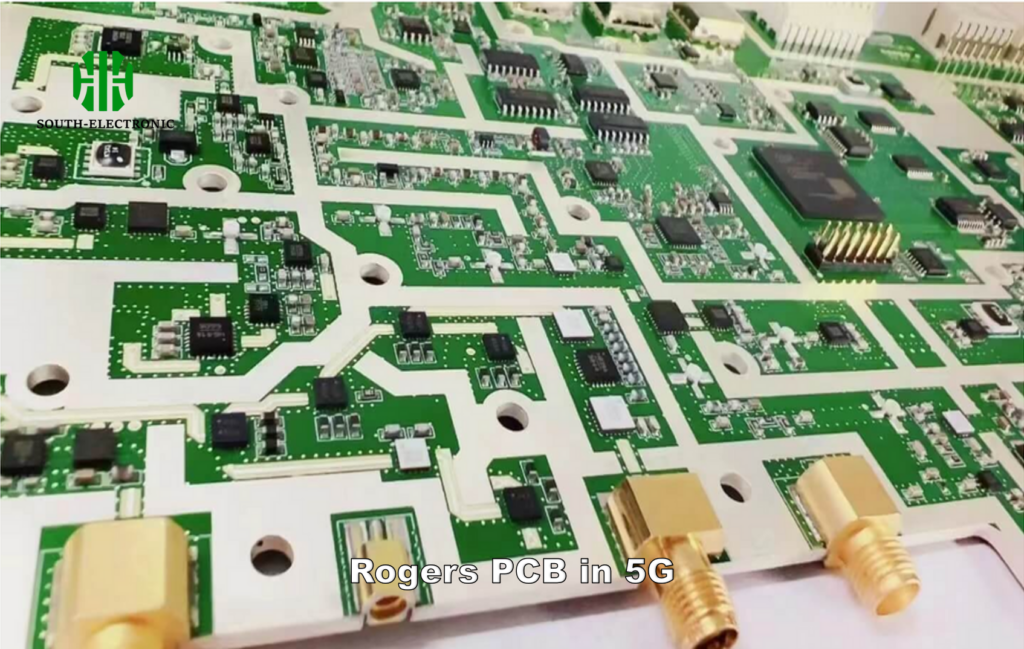
Rogers PCB outperforms regular boards in RF/microwave systems, 5G infrastructure, radar, satellite tech, and automotive electronics where minimal signal loss, strict thermal control, and stable dielectric properties are critical.
Understanding when Rogers shines solves half the battle. But choosing correctly impacts your entire project’s success. Now, let’s break down why it beats alternatives and how to avoid costly errors.
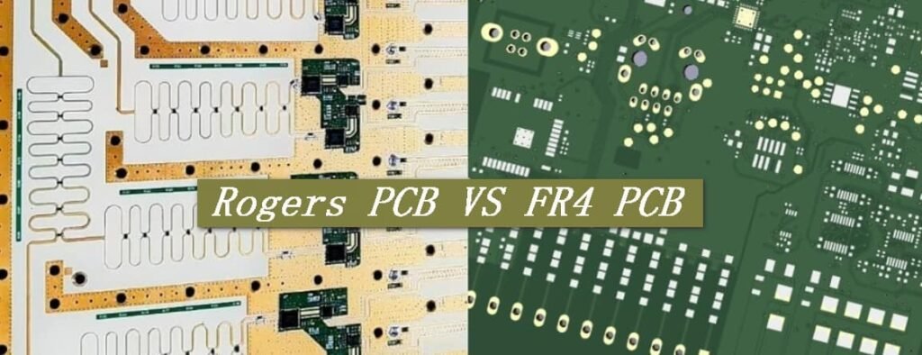
Why is Rogers better than FR4?
FR4 boards failing in your 5G prototype? Performance drops at high frequencies? Rogers offers superior signal integrity where FR4 falters. Your microwave designs need consistent material behavior.
Rogers laminates maintain stable dielectric constants across frequencies, reduce signal loss by 70% versus FR4, and offer near-zero moisture absorption. This prevents impedance mismatches in RF systems.
Critical performance differences
Rogers dominates in three key areas FR4 can’t match:
Thermal management
| Property | Rogers 4350B | Standard FR4 |
|---|---|---|
| Thermal Conductivity | 0.62 W/mK | 0.25 W/mK |
| CTE (ppm/°C) | 32 | 70 |
| Tg (°C) | >280 | 130-140 |
Rogers handles heat better during high-power transmissions. This prevents delamination in radar systems.
Signal integrity
FR4’s erratic Dk values cause phase distortion above 1GHz. Rogers keeps signals clean up to 40GHz. I’ve seen 5G base stations using Rogers achieve 0.15 dB insertion loss versus FR4’s 0.8 dB loss.
Environmental stability
Automotive radars face moisture and temperature swings. Rogers resists both better, maintaining constant impedance. FR4 absorbs humidity, changing performance mid-operation. Never risk signal drift in critical communications.
What Rogers PCB design mistakes should you avoid?
Struggling with unexpected signal loss? Rogers behaves uniquely. Common FR4 design habits backfire. Don’t let small errors ruin expensive boards.
Prevent impedance mismatches and delamination. Control etching and lamination processes precisely. Your millimeter-wave design depends on this.
Crucial design considerations
Three frequent errors degrade Rogers PCB performance:
| Drilling parameter issues | Mistake | Consequence | Solution |
|---|---|---|---|
| High drill speed | Resin smear on vias | Use 70% humidity soak | |
| Dull drill bits | Rough via walls | Replace after 500 hits | |
| No entry material | Board delamination | Use 0.1mm aluminum foil |
I once saw a satellite antenna fail from resin-clogged vias. Smooth via walls ensure consistent RF paths.
Copper treatment failures
Never use standard oxide treatments. Rogers requires nanostructured bonding surfaces. Plasma treatment works best. Acid cleaning etches too aggressively.
Thermal shock negligence
Rapid soldering temperature changes crack Rogers boards. Pre-bake boards at 125°C for 4 hours before assembly. Use gradual reflow profiles.
Which high-frequency laminate (Rogers, Taconic, PTFE) is best for 5G applications?
Choosing wrong laminate for 5G mmWave? Each frequency band demands different properties. Roger’s consistency often wins. But sometimes alternatives fit better.
For active arrays above 24GHz, Rogers RO3003™ delivers lowest loss. Below 6GHz, cost-effective Taconic RF-35 might work. Know your frequency sweet spots.
Material selection breakdown
Select laminates based on three performance pillars:
| Key properties for 5G | Material | Dk Stability | Cost Factor | Loss Tangent |
|---|---|---|---|---|
| Rogers RO4000™ | ★★★★★ | $$$ | 0.0027 | |
| Taconic RF-35 | ★★★☆☆ | $$ | 0.0018 | |
| PTFE w/filler | ★★☆☆☆ | $$$$ | 0.0013 |
Frequency range fit
Rogers RO3000™ series dominates 24-40GHz bands with ±0.02 Dk tolerance. PTFE suits fixed-frequency designs needing ultra-low loss. Taconic provides budget options under 6GHz where drift matters less.
Thermal vs electrical balance
Rogers uniquely couples electrical stability with thermal resilience. Automotive radars use RO4835™ for vibration resistance. For static indoor 5G nodes, Taconic saves cost. Satellite uplinks need Rogers’ temperature immunity.
Match materials to your specific use case—there’s no universal "best."
Conclusion
Choose Rogers PCBs for critical RF/microwave systems demanding precision. Avoid design pitfalls through controlled manufacturing. Select laminates based on frequency requirements. Performance justifies the cost.

