
Bad capacitor placement kills circuits. Noise spikes destroy signals. Systems crash unexpectedly. This is preventable with strategic positioning.
Place capacitors close to IC power pins for decoupling – 0.1μF ceramics within 2cm. Add bulk electrolytics near power inputs (10-100μF). Position bypass capacitors parallel to signal paths between noisy components and sensitive areas.
Proper positioning prevents disasters, but identification comes first. Not recognizing capacitor types causes design failures. Let’ts fix that issue now.
How to identify PCB capacitors, including reading codes and spotting faults?
Mystery components sabotage repairs. Misreading codes wastes hours. Damaged capacitors disguise themselves well.
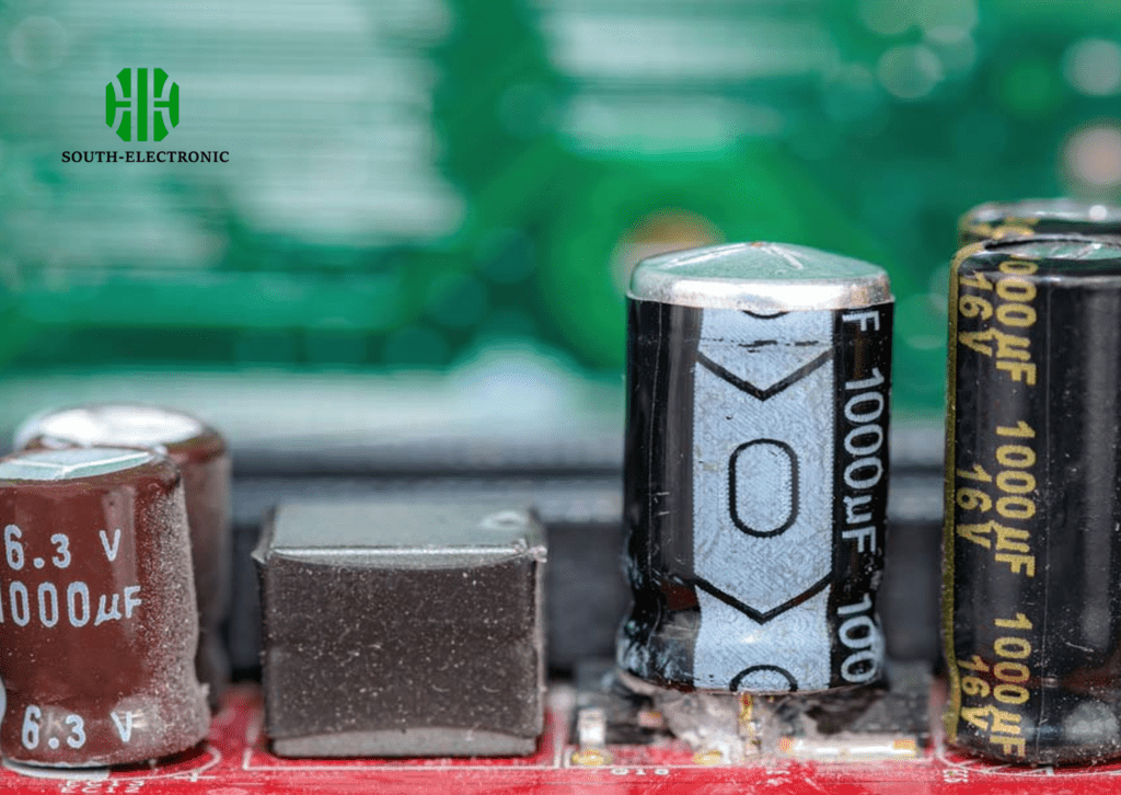
Identify ceramics by flat rectangles with numbered codes (104 = 100nF). Spot electrolytics through cylindrical bodies and voltage/C values printed sideways. Find tantalums as tear-drop shaped with polarity stripes.
Effective identification requires decoding markings and failure signs. I once replaced a swollen capacitor that kept resetting a microcontroller.
Three identification pillars
All capacitor identification relies on:
| Method | Visual Clues | Testing Approach | Common Fault Signs |
|---|---|---|---|
| Markings | 3-digit codes (e.g., 475=4.7μF) | Multimeter capacitance mode | Bulging tops, leaking fluid |
| Physical Shape | Rectangular ceramics, cylinder electrolytics | ESR meter readings | Burnt marks, cracks |
| Board Position | Near ICs = decoupling caps | Resistance check for shorts | Corroded leads, displacement |
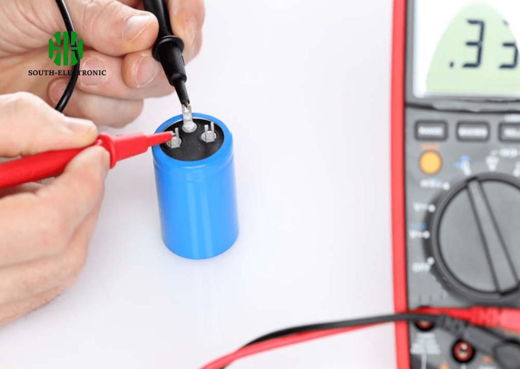
First, check component labeling. A "107K" ceramic means 100μF with 10% tolerance. Electrolytics show voltage ratings like "35V" beside capacitance. Next, examine body shapes – cracked ceramics often cause intermittent failures. Finally, measure: under 5Ω ESR is typically good; above 20Ω indicates replacement time.
Fault detection workflow
- Visual scan for bulges/leaks
- Test capacitance with multimeter
- Compare against marked values
- Verify ESR below component spec
Swollen capacitors mean immediate replacement. I fixed a motor driver by spotting a leaking 220μF capacitor near its power connector.
Now you can spot capacitor issues. Next comes selection science. Wrong specs guarantee failures.
What key factors can’t you ignore when selecting the right capacitor for your PCB?
Cost-driven choices cause malfunctions. Overlooking ripple current burns components. Ignoring temperature kills reliability.
Never compromise on voltage (150% above circuit max), temperature rating (match environment highs), ESR (lower for power paths), and lifespan (2000+ hours for critical systems).
Choosing capacitors demands balancing electrical needs with physical constraints. My solar controller failed until I switched to 105°C rated capacitors.
Key selection matrix
Consider these non-negotiable factors:
| Factor | High Importance For | Measurement Tips | Danger of Ignoring |
|---|---|---|---|
| Voltage | Power supply sections | Add 50% margin above max voltage | Exploding capacitors |
| ESR | High-frequency decoupling | Check datasheet at operating frequency | Overheating, voltage drops |
| Temperature | Automotive/outdoor devices | Verify both minimum/maximum ranges | Capacity reduction, short life |
| Tolerance | Timing circuits/filters | Stick to ±5% or better | Clock drift, signal distortion |
Voltage rating is most critical. A 12V circuit needs at least 18V capacitors for safety. ESR must match frequency demands – high-frequency circuits like switching supplies require ESR below 0.1Ω.
Physical dimension constraints
Measure space before choosing electrolytic sizes. In my drone project, 8mm-tall capacitors fit where 10mm ones short-circuited. Consider future component proximity – heat-generating parts degrade nearby capacitors.
You’ve selected optimal capacitors. Now decode when to use which type.
Ceramic vs. electrolytic vs. tantalum: which PCB capacitor type is best in which situations?
Random type selection wastes money and space. High-frequency noise defeats ceramics. Reverse voltage blows electrolytics.
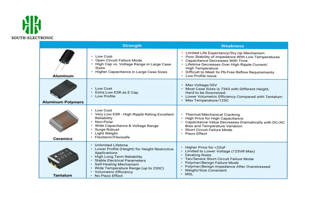
Use ceramics (0.1μF-10μF) near ICs for high-frequency decoupling. Choose electrolytics (10μF-10,000μF) where massive energy storage matters. Pick tantalums (1μF-500μF) for stable performance in compact spaces.
Each capacitor type serves unique roles in PCB ecosystems. I burned tantalums by placing them downstream of power switches.
Application decision table
Match capacitor technologies to circuit requirements:
| Type | Best Use Cases | Avoid These Situations | Key Strengths |
|---|---|---|---|
| Ceramic | >10MHz noise suppression | High voltage circuits (>50V) | Low cost, tiny size |
| Electrolytic | Power input stabilization | Below-freezing temperatures | High capacitance volume |
| Tantalum | Medical devices, aerospace | High ripple current paths | Stability, small footprint |
Ceramics dominate mobile device PCBs – their non-polarity prevents reverse-bias risks. Electrolytics serve power entry points where large capacitances absorb electrical surges. Tantalums shine in implantable medical devices requiring decades of reliability.
Performance trade-offs
Ceramics lose capacitance under DC bias. I compensated by specifying 22μF when only 10μF was needed. Electrolytics leak more current than tantalums – problematic for battery-powered designs. Compare cost vs performance: ceramic for budget designs, tantalum for life-critical systems.
Conclusion
Place capacitors strategically near noise sources and power pins. Select types and specs matching your circuit demands. Careful capacitor management ensures PCB reliability.


