
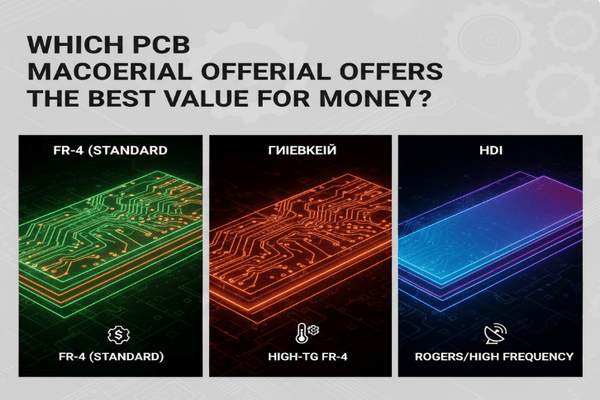
Trouble choosing the right PCB material[^1]? Worried about cost versus performance[^2]? Many engineers face this challenge, leading to design compromises.
The best value-for-money PCB material depends on your specific application needs, balancing performance requirements with budget constraints. While FR-4 is a common choice, its various grades offer different thermal performance[^3] and cost points.
Finding the sweet spot between cost and functionality is key to successful electronic design. Let’s explore the options to ensure your next project is both robust and economical, moving beyond just the surface.
What types of PCB materials are there?
Confused by the array of PCB materials available? Picking the wrong one can jeopardize your project’s reliability and cost. It’s a common pitfall.
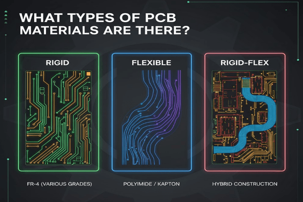
PCB materials broadly categorize into rigid, flexible, and rigid-flex, each with sub-types like FR-4[^4] (various grades), polyimide[^5], and ceramic[^6]. These offer distinct electrical, thermal, and mechanical properties[^7] for diverse applications.
When I first started designing, I thought all PCBs were more or less the same. Boy, was I wrong! Understanding the different types is fundamental to making informed decisions.
Understanding the Spectrum of PCB Substrates
PCB materials are not one-size-fits-all. They range from the very basic to highly specialized.
- Rigid Materials:
- FR-4 (Flame Retardant 4): This is the industry workhorse. It's a glass fiber reinforced epoxy laminate. My insights tell me that FR-4 isn't just one material; it has grades like TG130, TG150, and TG170. TG, or Glass Transition Temperature, indicates where the material softens significantly. A higher TG means better thermal stability. For instance, a TG130 FR-4 is suitable for general consumer electronics, while TG170 might be needed for more demanding automotive or industrial applications where heat is a factor.
- High-Tg FR-4: For applications needing better thermal performance, extending the life of components under higher operating temperatures.
- CEM (Composite Epoxy Material): CEM-1 and CEM-3 are common. CEM-1 is paper-epoxy, cheaper than FR-4 but single-sided. CEM-3 is a composite of woven glass fabric and paper, often used as a cheaper alternative to FR-4 for double-sided boards.
- PTFE (Polytetrafluoroethylene): Known for excellent high-frequency performance[^8], vital for RF and microwave circuits due to its low dielectric loss.
- Ceramic: Offers superior thermal conductivity and dimensional stability, ideal for high-power applications or environments with extreme temperature changes.
- Flexible Materials:
- Polyimide: The most common flexible PCB material. It can withstand high temperatures and is very durable. My first flexible design used polyimide, and its ability to bend without breaking was a game-changer for a compact device I was working on.
- Polyester (PET): A more cost-effective option for less demanding flexible applications, but with lower temperature resistance than polyimide.
- Rigid-Flex Materials:
- These combine rigid and flexible substrates, offering the best of both worlds. They allow for 3D packaging solutions, reducing the need for connectors and improving reliability.
| Material Type | Key Characteristics | Common Applications | Cost Range |
|---|---|---|---|
| FR-4 (Standard) | Good electrical properties, low cost, easy to process | Consumer electronics, general purpose | Low |
| FR-4 (High-Tg) | Improved thermal stability, higher temperature resistance | Automotive, industrial control, power supplies | Medium |
| PTFE | Excellent high-frequency performance, low dielectric loss | RF/Microwave circuits, high-speed digital | High |
| Polyimide | Flexible, high temperature resistant, durable | Flexible circuits, medical devices, aerospace | Medium-High |
| Ceramic | High thermal conductivity, dimensional stability | High-power LEDs, sensors, aerospace | High |
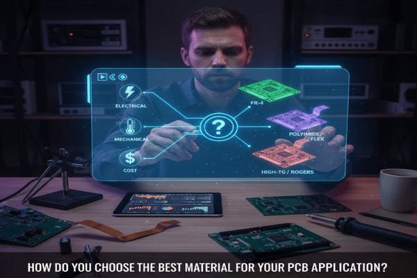
How do you choose the best material for your PCB application?
Struggling to pinpoint the ideal PCB material for your project? Selecting the wrong one can lead to performance issues or unnecessary expenses. It’s a common hurdle for designers.
Choosing the best PCB material involves a trade-off analysis of electrical performance (dielectric constant, loss tangent), thermal management (Tg, thermal conductivity), mechanical properties (flexibility, strength), and, critically, cost.
When I was first learning, I often picked materials based on what was easiest or cheapest. I quickly learned that understanding the application's demands is paramount. This insight helps you avoid costly re-spins later.
A Systematic Approach to Material Selection
Selecting a PCB material is not a simple task. It requires careful consideration of several factors.
- Electrical Performance:
- Dielectric Constant (Dk): Also known as relative permittivity. For high-speed digital and RF applications, a stable and low Dk is crucial to maintain signal integrity and controlled impedance. Variations in Dk can cause signal delays and reflections.
- Dissipation Factor (Df) / Loss Tangent: This measures the signal energy lost as heat within the dielectric material. For high-frequency circuits, a low Df is essential to minimize signal attenuation. Materials like PTFE excel here.
- Characteristic Impedance: The material's Dk and thickness, along with trace geometry, determine the impedance. Maintaining consistent impedance is vital for high-speed signals.
- Thermal Management:
- Glass Transition Temperature (Tg): As my insights state, FR-4 comes in various Tg grades (130°C, 150°C, 170°C). Above Tg, the material loses its rigid structure, becoming rubbery, which can cause dimensional instability. Choose a Tg significantly higher than your operating temperature.
- Thermal Conductivity: How well the material dissipates heat. For power electronics or high-density boards, materials with higher thermal conductivity can help prevent hotspots and improve component reliability.
- Coefficient of Thermal Expansion (CTE): This measures how much the material expands or contracts with temperature changes. A mismatch in CTE between the PCB and components can lead to stress and solder joint failures, especially in multilayer boards.
- Mechanical Properties:
- Flexibility: Does your design need to bend? If so, flexible materials like polyimide are necessary. Rigid-flex boards offer controlled flexibility in specific areas.
- Peel Strength: The strength of the bond between the copper trace and the dielectric substrate. This is important for robustness during manufacturing and in use.
- Tensile Strength: The material's resistance to breaking under tension.
- Cost: This is always a factor. High-performance materials typically cost more. You must balance the performance requirements with the budget. Sometimes, a slightly higher material cost can save significantly on failure rates or improve market competitiveness.
| Factor | Considerations | Impact on Design |
|---|---|---|
| Electrical Dk/Df | Signal integrity, speed, frequency | Controlled impedance, signal loss |
| Thermal Tg/CTE | Operating temperature, component reliability | Warpage, solder joint reliability, lifespan |
| Mechanical | Durability, flexibility, vibration resistance | Board shape, component attachment, manufacturability |
| Cost | Budget constraints, project profitability | Material choice, manufacturing process |
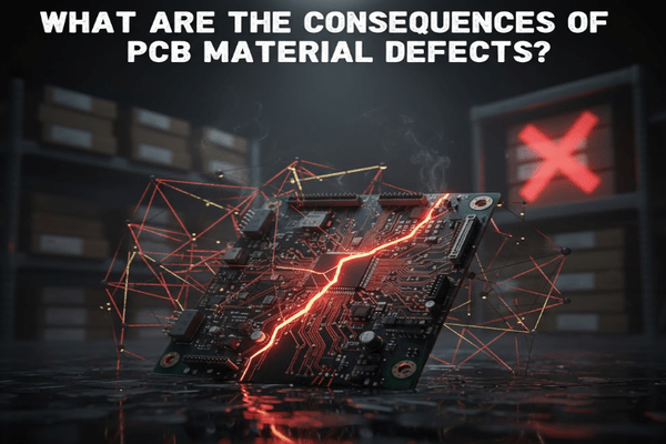
What are the consequences of PCB material defects?
Worried about your PCB designs failing unexpectedly? Material defects can cause catastrophic problems, leading to costly recalls and reputational damage. This is a critical concern.
PCB material defects can lead to short circuits[^9], open circuits, impedance mismatches, signal loss[^10], and reduced product lifespan, directly impacting performance and reliability. These issues often emerge during manufacturing or field operation.
I once worked on a project where we used a cheaper FR-4 grade to save a few cents. The boards started failing after a few months in the field due to thermal stress. The cost of replacing those units far outweighed the initial savings.
The Ripple Effect of Flawed Materials
Even minor imperfections in PCB materials can have far-reaching consequences.
- Electrical Failures:
- Short Circuits: Contamination or voids in the dielectric can lead to unintended electrical paths, causing components to overheat or fail.
- Open Circuits: Delamination or poor copper adhesion can result in broken traces, leading to non-functional connections.
- Impedance Mismatch: Inconsistent dielectric thickness or properties can alter characteristic impedance[^11], causing signal reflections in high-speed lines, leading to data corruption or reduced system performance.
- Increased Signal Loss: Higher Df values due to material impurities or moisture absorption[^12] can significantly attenuate high-frequency signals, making the circuit unreliable.
- Thermal Failures:
- Overheating: Materials with low thermal conductivity can trap heat, leading to premature component aging or failure, especially in power-dense designs.
- Delamination: If the operating temperature exceeds the material's Tg, the layers of the PCB can separate, leading to structural and electrical integrity loss. This is why choosing the correct Tg for FR-4 is crucial.
- Thermal Stress Cracks: Mismatched CTEs between different layers or between the PCB and soldered components can cause mechanical stress, leading to cracks in solder joints or even the board itself, especially after thermal cycling.
- Mechanical Failures:
- Reduced Durability: Weak adhesion or brittle substrates can make the PCB more susceptible to damage during assembly, shipping, or use.
- Warpage: Uneven expansion or contraction can cause the board to warp, making assembly difficult and potentially damaging components.
- Moisture Absorption: Some materials absorb moisture, which can degrade electrical properties and lead to delamination during reflow soldering.
| Defect Type | Potential Cause | Consequence | Mitigation Strategy |
|---|---|---|---|
| Short/Open Circuit | Voids, contamination, poor adhesion | Component failure, non-functional board | Strict material quality control, proper processing |
| Impedance Mismatch | Inconsistent Dk/thickness | Signal reflection, data errors | Uniform material properties, controlled stack-up |
| Overheating | Low thermal conductivity, high Df | Component aging, premature failure | Higher thermal conductivity materials, proper Tg |
| Delamination | Exceeding Tg, moisture absorption | Structural/electrical breakdown | Suitable Tg, moisture control |
| Warpage | Mismatched CTE, uneven material | Assembly issues, component damage | CTE matching, balanced layer stack-up |
Besides FR-4, what other high-performance materials can raise the bar for your designs?
Are your current FR-4 designs hitting a performance ceiling? Standard materials might be limiting your next-gen product's speed or thermal capabilities, leaving you looking for more.
Beyond standard FR-4, high-performance PCB materials like PTFE, polyimide, ceramic, and specialized hydrocarbon resins offer superior electrical, thermal, and mechanical properties, enabling higher frequencies, better thermal management, and extreme environment operation.
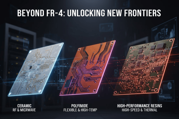
Moving beyond FR-4 felt like unlocking a new dimension in design. For a project involving high-frequency radar, I quickly realized that traditional FR-4 simply wouldn't cut it. This push into specialized materials completely changed my perspective on what was possible.
Elevating Performance with Advanced Substrates
While FR-4 is excellent for many applications, some designs demand more.
- PTFE (Polytetrafluoroethylene) / Teflon-based materials:
- These are the go-to for RF, microwave, and millimeter-wave applications. Their ultra-low Df (dissipation factor) means significantly less signal loss at high frequencies compared to FR-4. This directly translates to better signal integrity and power efficiency for wireless communications, radar, and satellite systems. I learned this firsthand when struggling with signal attenuation in a 5G prototype using FR-4; switching to a PTFE-based laminate solved the issue immediately.
- They also exhibit excellent Dk stability across a wide temperature and frequency range, crucial for predictable performance.
- Examples include Rogers Corporation's RT/duroid series and Arlon materials.
- Polyimide:
- While also a flexible material, rigid polyimide laminates offer superior thermal stability and chemical resistance compared to FR-4. They can withstand much higher operating temperatures, making them suitable for aerospace, down-hole drilling, or automotive under-hood applications.
- They also have good electrical properties, making them a viable option for high-reliability applications where FR-4 might degrade.
- Ceramic (e.g., Alumina, Aluminum Nitride):
- These materials boast extremely high thermal conductivity and excellent dimensional stability. They are indispensable for high-power electronics, LED lighting, and direct-chip-attach applications where heat dissipation is critical.
- Their low CTE (coefficient of thermal expansion) closely matches that of semiconductor chips, reducing thermal stress on solder joints.
- Hydrocarbon Resin Systems (e.g., Panasonic MEGTRON series, Isola I-Terra):
- These are often used as high-performance alternatives to standard FR-4 for high-speed digital applications (e.g., servers, data centers). They offer lower Dk and Df than high-Tg FR-4, improving signal integrity and reducing latency for very fast data rates.
- They bridge the gap between FR-4 and pure PTFE materials, offering a good balance of performance and processability.
- Modified Epoxies / PPO (Polyphenylene Oxide) blends:
- These often enhance the electrical performance of traditional FR-4 without going to the expense of PTFE. They offer improved Dk and Df characteristics, making them suitable for mid-range high-speed applications.
| Material Family | Primary Benefit | Key Applications | Compared to FR-4 |
|---|---|---|---|
| PTFE-based | Ultra-low Df, Dk stable | RF/Microwave, 5G, Radar | Much lower loss, higher cost |
| Rigid Polyimide | High thermal/chem resistance | Aerospace, automotive, high-temp industrial | Higher Tg, better durability |
| Ceramic | High thermal conductivity | High-power LEDs, sensors, aerospace | Superior heat dissipation |
| Hydrocarbon Resins | Low Dk/Df, high-speed | Data centers, servers, high-speed digital | Better signal integrity |
Conclusion
Choosing the right PCB material balances cost and performance, with FR-4 grades for most, and advanced materials for high-speed, thermal, or harsh environments.
[^1]: Explore this link to understand the various PCB materials and their applications for optimal design. [^2]: Discover strategies for balancing cost and performance when selecting PCB materials. [^3]: Discover the importance of thermal performance in PCB design and how it impacts reliability. [^4]: Learn about FR-4, its grades, and why it's a popular choice for PCB manufacturing. [^5]: Explore the benefits of polyimide as a flexible PCB material and its applications. [^6]: Learn about ceramic materials and their superior thermal conductivity for high-power applications. [^7]: Discover the key mechanical properties that influence PCB durability and performance. [^8]: Learn about materials that excel in high-frequency applications and their benefits. [^9]: Explore the common causes of short circuits in PCBs and how to prevent them. [^10]: Understand the causes of signal loss in PCBs and strategies to mitigate it. [^11]: Understand the concept of characteristic impedance and its role in high-speed PCB design. [^12]: Learn about the impact of moisture absorption on PCB reliability and performance.


