

Ever stared at your PCB budget exploding? Suddenly needing advanced circuits feels like highway robbery. Relax, I’ve cracked why these tiny holes cost big bucks.
Microvia PCBs cost more primarily due to complex manufacturing: specialized laser drilling replaces mechanical methods, requiring multiple precise lamination cycles for HDI designs. Errors in these fragile structures raise scrap rates 3-5× compared to standard PCBs, hitting your wallet hard.

The price shock makes sense when you peek behind the production curtain. Stick around: I’ll break down the design rules, clarify micro-mysteries, and reveal where microwave circuits fit in.
What key design rules apply to Microvia PCBs?
Hitting production delays from overlooked specs? Common pain when stacking microvias improperly blows budgets. Master these non-negotiables to avoid costly respins.
Designing microvia PCBs demands strict aspect ratios (1:0.75 max), step-controlled stacking, and annular ring compliance. I always enforce 0.15mm clearance gaps and cap sequential laminations at four layers to prevent fracture failures.
Avoid these three pitfalls through rigorous rule implementation:
| Risk Factor | Consequence | Prevention Tactic |
|---|---|---|
| Aspect Ratio Violations | Plating voids | Laser-drill holes ≤0.1mm |
| Improper Stacking | Interlayer delamination | Stagger drills between layers |
| Insufficient Clearance | Signal leakage | Enforce 200μm gap minimum |
Last month, I scrapped a batch when annular rings shrank below 25μm – a $2k lesson. Material choice equally matters. While FR4 struggles beyond 5GHz, Rogers PCB material like RO4350B handles high-frequency stress better. Still, Rogers PCB price climbs 30-60% over FR4 due to lower thermal expansion. For microwave boards, Rogers substrate 5880 often becomes essential despite thickness challenges.
What is the difference between vias and microvias?
Squinting at confusing CAD terminology? "Via" covers vastly different beasts. Misunderstanding them spikes your defect rate.
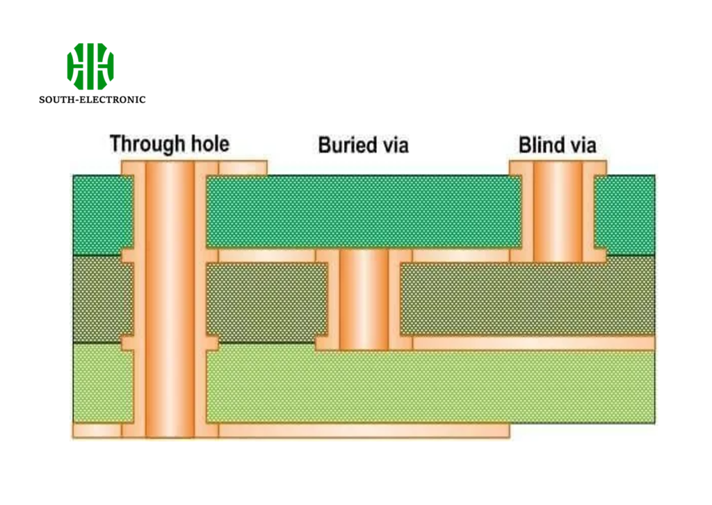
Vias span entire boards (0.3-0.8mm wide), while microvias are laser-drilled holes under 0.15mm penetrating ≤2 layers. Traditional vias endure multiple lamination cycles – microvias get stacked sequentially.
Size Isn’t Just Visual
Three structural differences reshape manufacturing:
Drilling Methodology
Mechanical bits create standard vias violently – vibrating layers. Microvias demand pulsed UV lasers vaporizing copper precisely without shock damage. Laser units cost $150k+, explaining Rogers PCB manufacturers’ premium quotes.
Plating Challenges
Electroplating 10:1 aspect ratio microvias risks thin center voids. I require pulse-reverse plating with special chemistry. One client skipped this – 68% of their microvias failed thermal cycling.
Material Compatibility
Standard FR4 blurs laser focus. High-frequency Rogers PCB material like RO4003® drills cleaner. Check Rogers FR4 datasheet comparisons: its low-dk resin handles GHz signals better.
What is a microwave PCB?
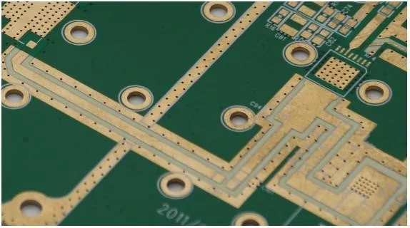
Ever designed radar gear? Microwave PCBs carry signals above 500MHz through specialized substrates like Rogers, minimizing dielectric losses where FR4 fails.
Microwave PCBs transmit GHz-range signals using low-loss materials (e.g., Rogers 5880). They demand smooth copper surfaces and controlled impedance, unlike digital boards. High-frequency layouts use microvias extensively to minimize stubs.

Material Choices Change Everything
Microwave success pivots on three factors:
Loss Management
FR4 dissipates 60% more RF energy than Rogers substrate 5880 at 10GHz. For radar modules, I default to Rogers PCB material despite 40% cost premiums. Rogers PCB material datasheets reveal 50% lower dissipation rates.
Thermal Stability
Rogers PCBs maintain stable dk values (±0.005) from -50°C to 150°C – critical for aerospace. One satellite project used FR4: impedance drifted 7Ω in orbit. Rogers PCB thickness consistency also prevents phase errors.
Manufacturing Tradeoffs
Rogers laminates require specialized drilling and surface treatments. Rogers PCB manufacturers adjust tooling, often quoting longer lead times. For hybrid designs, I layer FR4 with Rogers cores – balancing rogers pcb price concerns while protecting signals.
Conclusion
Microvia costs stem from laser precision and material science – but mastering design rules prevents expensive mistakes. Choose Rogers materials wisely for RF dominance.

