

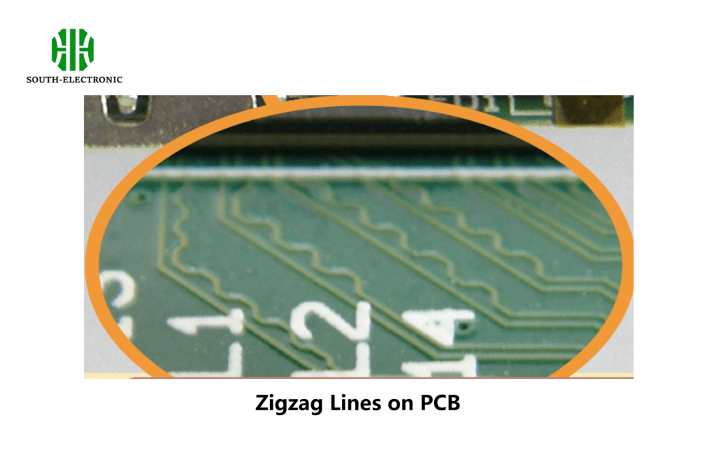
Why Are There Zigzag Lines on PCBs?
Zigzag lines on PCBs ensure that signals reach their destination at the same time by equalizing the length of conductive traces. These squiggly lines, also called snakey lines, help keep the signals in time, get rid of noise, and make sure the two signals in a pair are the same in high-frequency circuits. This is really important for sending data fast and making sure your fancy electronics work right.
Why Are Some PCB Traces Squiggly?
The squiggly, zigzag, or serpentine patterns you see on PCB traces are not just there for looks. They are there for a reason, and that reason is timing and signal integrity. As data transmission rates increase, the timing of signals becomes more and more important. The squiggly lines ensure that all the signals in a data bus get to their destination at the same time. They balance the trace lengths so that all the signals get there at the same time, even when the circuit layout constraints would make that impossible.
Visual Explanation
Below is a visual representation of how zigzag traces balance the signal length between different traces:
Why Timing Matters in High-Speed PCBs
High-speed circuits require precise timing to avoid skew (a mismatch in signal arrival times). Skew can cause data errors, especially when dealing with parallel data buses or differential pairs. The goal of zigzag lines is to avoid these timing mismatches.
What Do Zigzag Lines on PCBs Represent?
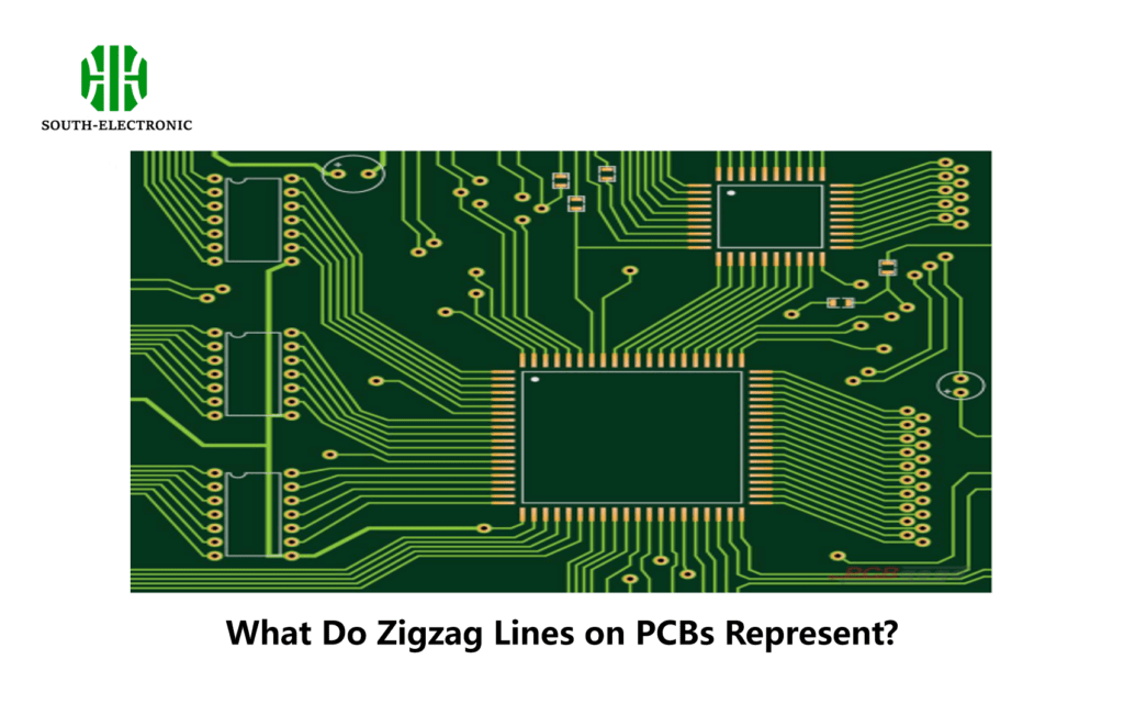
Wavy lines, or squiggly lines, are used to even out the lengths of traces. This is necessary when you’re routing traces on a multi-layer PCB and you don’t have enough room to make the traces straight. By adding extra length in a wavy pattern, you make sure that the signals travel the same distance across all the traces, which prevents skew.
Common Scenarios
- Data Buses: Ensuring that all data signals arrive at the same time.
- Differential Pairs: Maintaining the same length for each signal in the pair for balanced impedance.
- High-Speed Interfaces: HDMI, USB, and other high-speed interfaces rely heavily on zigzag traces to prevent timing errors.
How Do Zigzag Lines on PCBs Help with Signal Timing?
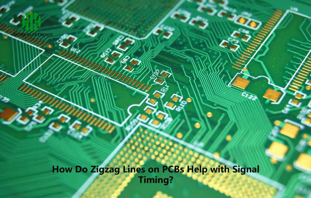
In high-frequency PCB designs, even small differences in trace lengths can cause significant timing issues. When signals do not arrive at their destination simultaneously, signal skew can occur, leading to data corruption. The longer a signal path, the greater the risk of these timing differences. Zigzag lines on PCBs help extend shorter traces to match the length of longer traces, thus avoiding these issues.
Timing Differences in PCB Traces
| Trace Length (mm) | Signal Speed (ps/mm) | Arrival Time (ps) |
|---|---|---|
| 50 | 5 | 250 |
| 55 | 5 | 275 |
| 65 | 5 | 325 |
As shown in Table , even a small increase in trace length can affect the signal’s arrival time, leading to potential errors in high-speed circuits.
Why Is Impedance Matching Important in PCB Design?
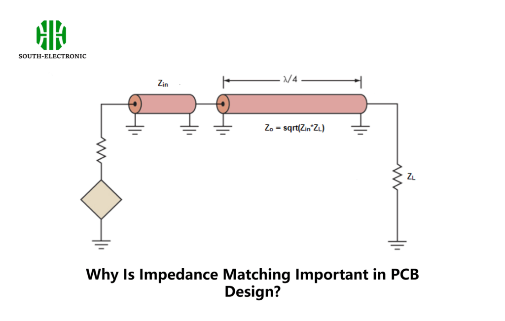
Impedance is a critical factor in ensuring that signals can travel cleanly across a PCB without distortion. When the impedance of a trace is not matched with the connected components, reflections can occur, which degrade the signal quality. Zigzag lines help maintain consistent impedance across differential pairs, particularly in high-speed circuits.
Maintaining Impedance with Zigzag Lines
If one of the traces in a differential pair is shorter, adding zigzag lines can equalize the length, thus ensuring that both traces have the same impedance. This prevents signal degradation and allows the circuit to function at higher frequencies without losing signal integrity.
Signal Integrity and Noise Reduction with PCB Zigzag Lines
Zigzag lines play a key role in maintaining signal integrity in high-speed circuits. As data transmission speeds increase, the likelihood of signal distortion due to reflections, noise, and timing mismatches also increases. Serpentine traces help mitigate these risks by ensuring that all signals in a bus or differential pair arrive simultaneously.
Impact of Trace Length on Signal Integrity
| Trace Length (mm) | Impedance Mismatch (%) | Signal Distortion (dB) |
|---|---|---|
| 50 | 1 | 0.1 |
| 55 | 2 | 0.3 |
| 65 | 4 | 0.5 |
Table demonstrates how longer traces, when not matched in impedance, can lead to greater signal distortion, reducing overall performance.
In short, zigzag lines help modern PCBs meet the demanding requirements of high-speed data transmission by balancing trace lengths, controlling impedance, and reducing noise. Whether you’re working on a simple hobby project or a complex B2B product, you need to understand signal integrity and trace routing.


